| |
 |
| | | |
| |
Introduction |
|
| | | |
| |
The power amplifier is a solid state device based on the ESP Project 101A (P101) amplifier, a well regarded design in the DIY HiFi community. This page describes the amplifier made during the second round; the first amplifier is described here. |
|
| | | |
| |
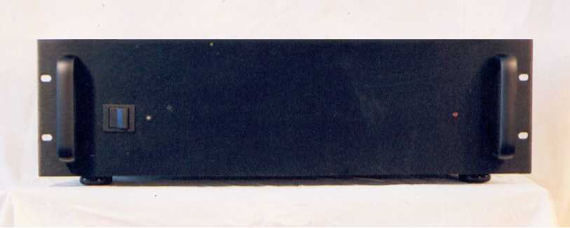
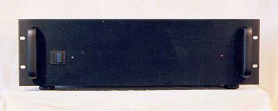
The amplifier is housed in a 3U rack case. The only features on the front of the amplifier are the on/off switch, a blue LED indicator light next to the switch, and a red LED clipping indicator light on the opposite side. |
|
| | | |
| |
 |
| | | |
| |
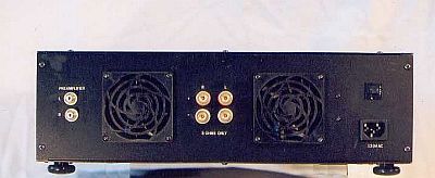
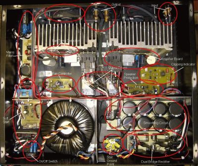
From left to right in the photo above, the back of the amplifier has two preamplifier-in RCA jacks; a large fan; four, 5-way, speaker-out terminals; a second fan; a 6 A circuit breaker (top); and an AC power receptacle (bottom). All input and output jacks are gold-plated. |
|
| | | |
| |
 |
| | | |
| |
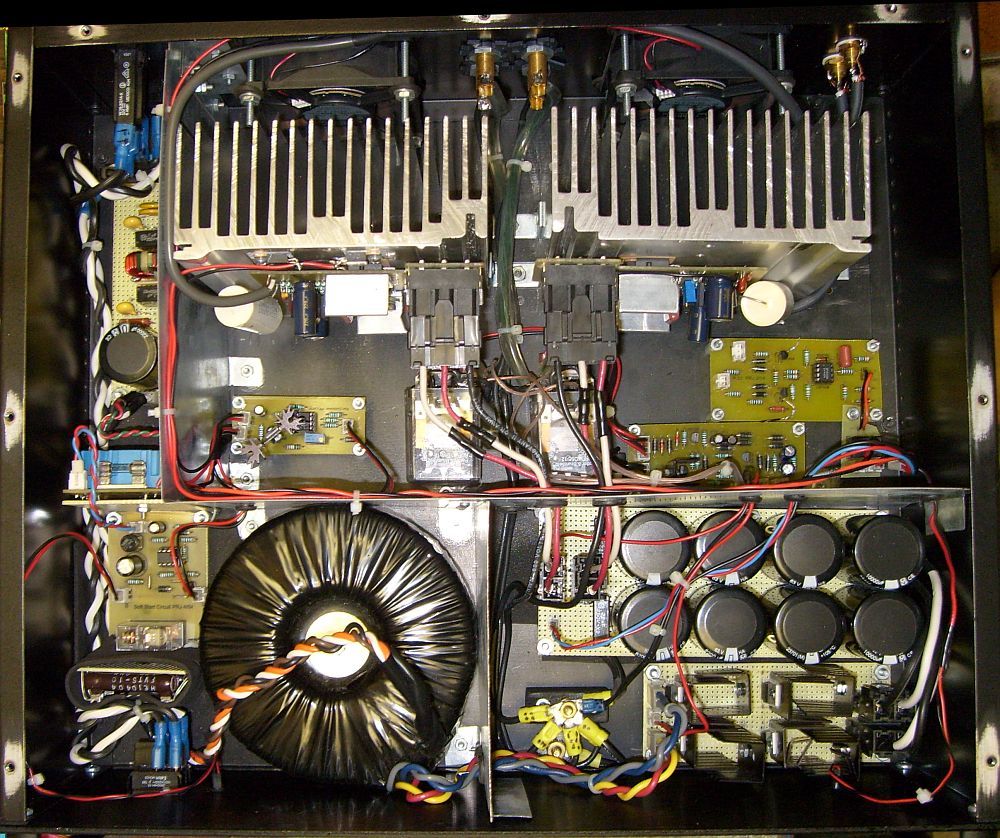
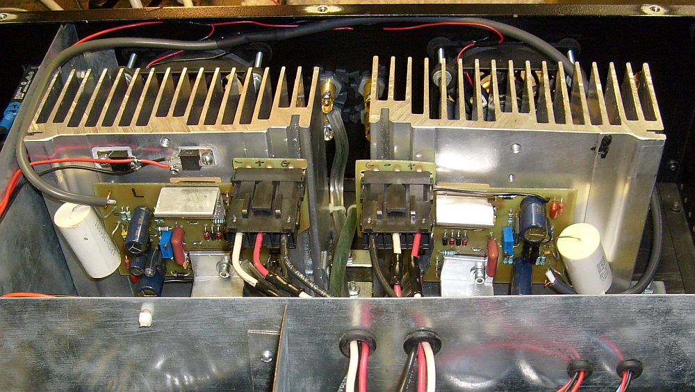
Inside the amplifier case you can see the following, as shown in the above photo:- The AC mains filter along the upper left edge
- The soft-start circuit and transformer in the lower left quadrant
- The power supply in the bottom right quadrant, including the smoothing circuit, rectifying bridge board, and floating star-ground point
- From right to left in the middle section (between the shield and the heat sinks) is the fan controller circuit board, two large output relays, the clipping indicator circuit board (top), and the speaker protection circuit board (bottom)
- Two large, vertically-mounted heat sinks with the amplifier boards attached
- Two, 12 VDC, 80 mm cooling fans on the back panel, one directly in front of each heat sink
|
|
| | | |
| |
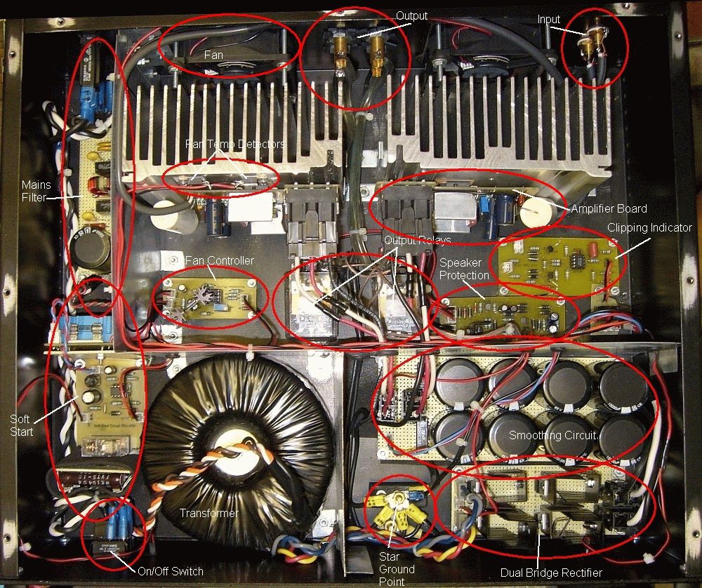
The picture below labels the various components (click to enlarge): |
|
| | | |
| |
 |
| | | |
| |
Grounding |
|
| | | |
| |
The amplifier uses a single star-grounding scheme. The floating star point can be seen at the bottom center of the above photo. The ground wires from each circuit board, as well as the negative speaker terminals and the power supply cap grounds, are collected at the star point. A single cable then connects the star point to the chassis with a bolt between the star point and the front panel. Input signal grounds are not connected to the amplifier boards, rather the cable shields are routed to the star-ground point along side of the circuit ground wires. |
|
| | | |
| |
AC Mains Circuits |
|
| | | |
| |
 |
| | | |
| |
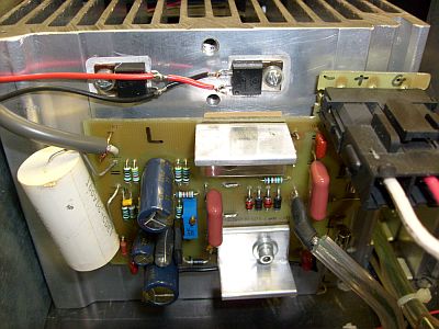
Both the hot and neutral AC mains are routed with 16 AWG wires from the AC receptacle on the back panel to the high-inrush rocker switch on the front panel, then back through the 6 A circuit breaker on the back panel (hot only), and into a mains filter built on a piece of perf-board. To remove noise above about 76 KHz, the filter uses four 2.2 nF Y2/X1 ceramic capacitors from hot and neutral to ground. Two 100 nF X2/Y metallized film capacitors, two 130 VAC MOVs, and a 1 MOhm resistors are placed across the mains. The 2 mH, 6.6 A, common-mode choke, shown in the above photo of the filter board, was included to eliminate common-mode noise from the mains, but was later disconnected because it clearly made the amplifier sound flat and lifeless. The large, low-voltage, high ripple-current, 22,000 uF electrolytic capacitor, protected by two opposite-oriented, high-current diodes, forms a "DC Trap" that eliminates an annoying 60 Hz buzz in the transformer caused by stray DC current on the AC mains. |
|
| | | |
| |
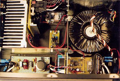
After leaving the filter, the AC mains current is run through a high-power relay that is controlled by a "soft-start" circuit. The soft-start circuitry and relay are contained on the single horizontal PCB in the lower right of the above photo. The soft-start circuit (based on ESP Project 39) routes the AC current through three, parallel, high-powered (12 W), 100 Ohm, wire-wound resistors (brown with white writing mounted on a vertical piece of perf-board on the right side of the soft-start board directly below the transformer in the above photo). The current is run through the resistors for about one-third of a second while the transformer and power supply capacitor bank is initially charged after turn-on. This dissipates the "inrush" current that could otherwise blow fuses, trip breakers, and burn up the power switch. After the third of a second, the relay trips and the AC current bypasses the resistors and is run directly to the transformer. The soft-start circuit is powered by its own, small, 5 VA, 9 VAC transformer that is mounted on a vertical piece of perf board attached to the left side of the soft-start board in the above photo (blue colored). The 9 VAC output is rectified to 12 VDC on the soft-start PCB to power the soft-start circuit, and it is also used to power the front panel indicator LED, and the fan control circuit, thereby eliminating any chance for fan or diode noise to get into the amplifier power supply. |
|
| | | |
| |
The soft-start circuit feeds the AC current to the Plitron 500 VA toroidal transformer that takes up the lower middle part of the amplifier case, and contributes more than half the weight of the amplifier (most of the rest comes from the heat sinks). The transformer has two, independent 30 VAC secondaries that are run to the large board containing the dual diode bridges shown in the photo below (the secondaries are not combined to form a 0 V reference ground at this point; the reference ground is not created until after the bridge rectifiers). |
|
| | | |
| |
The AC mains filter, soft-start circuit, transformer, and power supply are separated from the amplifier circuits by a galvanized-steel shield, as shown in the above two photos. As with the preamplifier, the shield is electrically connected to the top, sides, and bottom of the case, thereby creating a "Faraday Cage" that shunts any radiation emitted by the AC and power supply components (such as the transformer and diodes) to the chassis ground so they do not add noise to the amplifier signal. There is also a shield between the transformer and the diode bridge and capacitor bank that protects the DC rails from AC-generated radiation. |
|
| | | |
| |
Power Supply |
|
| | | |
| |
 |
| | | |
| |
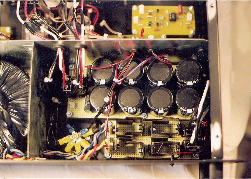
The diode bridge board, in the bottom right corner of the above photo, actually contains two independent bridges, one for each secondary, mounted on a single piece of perf-board. Each bridge uses four Fairchild MUR1560 ultra-fast, soft-recovery, 15 A, 600 V rectifier diodes, each with its own small heat sink. The DC output from the bridges is fed to the smoothing board directly above the bridge board that contains one 10,000 uF and three 8,200 uF Panasonic (TSHA series) electrolytic capacitors per rail (69,200 uF total). The resulting DC current is further smoothed with 220 nF metallized film caps before being fed to the amplifier boards. The (+) output of one of the smoothing circuits is combined with the (-) output of the other to form a common 0 VDC reference that connects to the star-ground point. The other two outputs produce +/- 42.7 VDC unloaded, and about +/- 41 VDC loaded. Connections are also provided to supply (+) DC power to the speaker protection circuit, and (+/-) DC power to the clipping indicator circuit. |
|
| | | |
| |
As shown here, my oscilloscope tests found that the +42 VDC rail shows 15 mV of ripple (about 0.04% of the supply voltage), and the -42 VDC rail shows 7 mV (about 0.02% of the supply voltage). The supply originally measured more than 30% higher ripple, but I inserted 0.1 Ohm, 5 W resistors in series on the two (+) traces of the smoothing circuit, midway between the four smoothing capacitors, and that lowered the ripple to the current values. |
|
| | | |
| |
P101 Amplifier Circuits |
|
| | | |
| |
 |
| | | |
| |
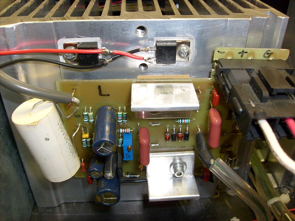
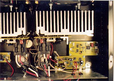
The two P101 amplifier boards are shown in the above photo attached to their heat sinks. Each channel uses its own P101 board, and each is mounted to its own heat sink. The photo below shows a close-up of the left channel board. |
|
| | | |
| |
 |
| | | |
| |
The boards are secured to the heat sinks with rigid, aluminum angle-irons that are held very tightly by bolts with lock washers. The bars hold the output transistors, located under the amplifier boards, firmly against the heat sinks for maximum heat transfer. Mounted vertically, the heat sinks are cooled (when necessary) by two automatic, temperature-controlled fans set to turn on at 40 degrees C (in the past two years the fans have never come on, and the heatsinks get only very slightly warm to the touch, unlike the P3A boards that utilized the fans virtually every time I turned it on). The bottom plate of the case is perforated beneath the heat sinks to add ventilation. The fan controller board (ESP Project 42) is mounted in front of the left-side heat sink, and can be seen in the AC Mains section photo above. The board is powered by a 12 VDC feed from the soft-start circuit board. Two TO-220 diodes, used as temperature sensors, are mounted on the left heat sink immediately adjacent to the amplifier circuit board,as shown in the close-up photo above. A trimmer pot on the controller board is used to adjust the fan turn-on temperature. The Panasonic 80 mm fans are run at 9 to 10 VDC, and are virtually inaudible. |
|
| | | |
| |
I found that one of the fans turned on at a slightly lower voltage than the other, and thus turned on a little sooner than the other, so I put that one opposite the amplifier heat sink without the heat-sensing diodes. |
|
| | | |
| |
Note the very large, white, 10 uF polypropylene input capacitors (C1) on each amplifier board. The Miller caps (C4 and C6) are 600 V polystyrene. The input wire is shielded cable from decent-quality commercial interconnects. The wire from the amplifier output through the relays to the speaker-out terminals is 12 AWG stranded copper ("zip") wire. |
|
| | | |
| |
Speaker Protection and Clipping Indicator Circuits |
|
| | | |
| |
 |
| | | |
| |
The photo above shows two PCBs between the right-side heat sink and the power supply shield: the clipping indicator circuit board (top) and speaker protection and muting circuit board (bottom). |
|
| | | |
| |
The speaker protection circuit (ESP Project 33) protects the speakers in case of an amplifier fault. Failure of the output transistors can create a dead-short that sends the full rail voltage (41 VDC) to the amplifier output, which, at 3 A, is more than enough juice to destroy the speakers before the fuses on the amplifier boards blow. The circuit protects the speakers by instantly switching off a pair of sealed, industrial-strength relays (and thereby cutting off the amplifier output to the speaker terminals) when any DC current is detected in the amplifier output. The input to the circuit is suppled from two wires that split from the amplifier output wires at the relay-in contacts. The circuit also has a one second delay on turn-on before the relays are energized, and it disconnects the relays instantly when the amplifier is turned off. This keeps the clicks, pops, and thumps from the amplifier turn on/turn off from going out to the speakers. These relays are huge, and when they click on and off, you hear it! |
|
| | | |
| |
The clipping indicator circuit (ESP Project 23) was installed between the speaker protection board and the right-side heat sink. When I first tested it, it worked fine until the amp warmed up, then the red LED began blinking at low volume levels. As a result, I disconnected it, as shown in the above photo. Later, I discussed it with Rod Elliot at ESP, and he figured that the ambient temperature rise was the culprit, and he advised changing a resistor value and adding resistors to the collectors of the switch transistors. That seemed to fix it, although eventially the red LED began to turn off and on at seemingly random times, so I disconnected it again. However, because I rarely turn the volume up past about one-third, and never past about one-half (and that is LOUD), I don't think that clipping with this amplifier and these speakers in my smallish listening room is, thankfully, an issue. |
|
| | | |
| |
Cables, Wires, and Connectors |
|
| | | |
| |
All DC power leads to the amplifier boards, as well as ground cables, are 12 AWG solid copper wires and use Molex Mini-Fit Senior 50 A connectors. Low power DC supplies use 3 A Molex-style plastic connectors with gold-plated contacts. AC connections use Fast-On quick disconnects, or 9 A Molex Mini-Fit Junior plastic connectors with gold-plated contacts. All signal lead connections, including the input shielded wires and the 12 AWG relay contacts and output terminals, are soldered. |
|
| | | |
| |
Other Notes |
|
| | | |
| |
In order to keep as much circuitry as possible out of the signal path, the amplifier has no short-circuit or thermal protection. The speaker protection circuit protects the speakers in the event of an amplifier fault, but it does not protect the amplifier itself. Shorting the input jacks or the speaker-out jacks (by plugging or unplugging cables while the amplifier is turned on, for example), can literally blow-up the amplifier (unfortunately, I have done it). The fans will attempt to cool the amplifiers if they get too hot, but there is no circuit to shut the amplifier off if it overheats. |
|
| | | |
| |
Conclusion |
|
| | | |
| |
And finally, how does it sound? Utterly superb! It sounds clear and bright, very open (you know, "airy") with no hum, buzz, noise or distortion of any kind. The P101 boards sound noticeably better than the P3A boards. The most noticeable imporvement is that the mid to upper bass is much clearer, and the highs are smoother with less harshness. It also sounds a little better than the first amplifier (also with P101 boards), presumably because the power supply and cable management is significantly better in all respects. The amplifier also tests very nicely, as shown here with the oscilloscope tests. |
|
| | | |
| | | |
| |  | |
| | | |
| | | |