| |
 |
| | | |
| |
Introduction |
|
| | | |
| |
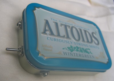
Although I already built a so-called "portable" headphone amplifier before, described here, I wanted to build a truly portable headphone amplifier that I (or more accurately, one of my sons) could carry in their pocket to improve the sound of their IPod or Zune. So, I designed the whole enchilada (power supply, amplifier circuit, switches, jacks, and 9V battery) to fit snugly in an Altoids box. |
|
| | | |
| |
Like the other portable headphone amplifier, this one uses the famous CMoy design as described on the old headwize.com site that appears to be gone now. My goal for the project (besides cramming it in an Altoids box) was to make it as cheaply as possible using as many leftover parts as I could. I ended up paying only about $14 at Radio Shack for the input and headphone jacks, a mini toggle switch, the battery connector, and a 1 foot patch cord to go between the amplifier and the IPod. Everything else came from my spare parts collection. |
|
| | | |
| |
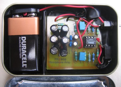
You can see the inside of the amplifier in the photo below. The circuit board was made as small as possible, and it barely fit. I had to really bend the jack and switch terminals around to keep them from interfering with each other and the components on the board. I insulated the inside of the case with electricians tape (several layers) and the PCB just sits on the tape. |
|
| | | |
| |
 |
| | | |
| |
Power Supply |
|
| | | |
| |
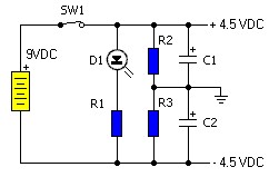
The power supply is the standard CMoy power supply shown below, except that I eliminated the LED, and the resistor that went with it (R1). The schematic below is borrowed from the Headwize Website: |
|
| | | |
| |
 |
| | | |
| |
The power supply is fed with a 9V battery, and it uses a very simple 4.7K resistor network (R2 and R3) as a rail splitter to produce a clean +/- 4.5 VDC, more or less. I didn't have two of the recommended 220uF capacitors on hand (C1 and C2), so I used six 100uF capacitors instead. I also added a 10uF electrolytic and a 100nF ceramic bypass capacitor from each rail to ground. |
|
| | | |
| |
Headphone Amplifier Circuit |
|
| | | |
| |
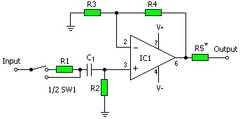
The amplifier also uses the standard CMoy design, with only a few modifications. For example, I did not use an input switch, just a 100K input resistor (R1). I used 47 ohms for the output resistor (R5), and I put the output resistor outside of the feedback loop, instead of inside like the schematic shows. I also used a 1uF film input capacitor (the blue boxes) instead of 100nF, so the low-pass filter created by the capicitor and a 100K resistor to ground (R2) now has a -3 dB value of about 3 Hz, instead of 15 Hz. I stuck with the 10K (R4) and 1K (R3) resistor pair, giving a gain of 11. The opamp is an OPA2134. Again, the schematic shown below is borrowed from the Headwize Website: |
|
| | | |
| |
 |
| | | |
| |
Conclusion |
|
| | | |
| |
How does it sound? Very good indeed; surprising for such a simple device. No hum, no buzz, no hiss; very quiet. |
|
| | | |
| |
I enjoyed making this so much that I made a second one, in a red Altoids box, that my son used to listen to music on his computer. |
|
| | | |
| |
Back |
|