| |
This page shows the results of testing the Gilmore "Dynalo" headphone amplifier (described here) with the borrowed oscilloscope (described here). |
|
| | | |
| |
Power Supply Measurements |
|
| | | |
| |
First, I measured the power supply, both the +16 VDC and -16 VDC rails. I measured the power supply with no input and no load, and with a 0.5 V signal from the signal generator as input (at 100 Hz, 1 KHz, 10 KHZ, and 100 KHz), and a 220 Ohm resistor (to simulate a pair of headphones) as a load on the output. Lots of combinations to test. |
|
| | | |
| |
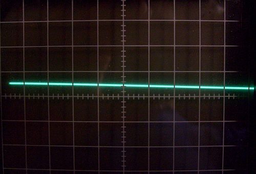
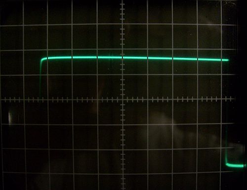
In almost every case, the result was the same. The signal was flat at the lowest, most sensitive voltage setting (10 mV/cm), with no hint of ripple, noise, or oscillation. As an example, below is the +16 VDC rail with a 1 KHz 0.5 V input and a 220 Ohm load measured at 10 us/cm and 10 mV/cm: |
|
| | | |
| |
 |
| | | |
| |
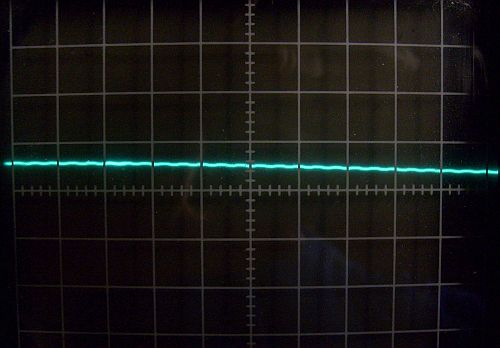
However, some ripple was detected at the 1 KHz input frequency. The following photo shows the +16 VDC rail with a 1 KHz 0.5 V input and a 220 Ohm load measured at 2 ms/cm and 10 mV/cm: |
|
| | | |
| |
 |
| | | |
| |
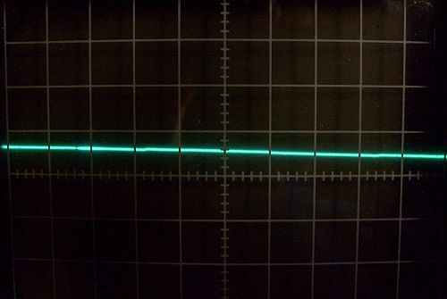
As you can see, there was a ripple of less than 0.5 mV at about 160 Hz. The -16 VDC rail showed the same thing. The ripple was not present with no input or load.The ripple disappeared with a 10 KHz and 100 KHz input frequency, and was barely visible at lower frequencies, as shown below (+16 VDC rail with a 100 Hz 0.5 V input and a 220 Ohm load measured at 2 ms/cm and 10 mV/cm): |
|
| | | |
| |
 |
| | | |
| |
I do not understand why there would be slight ripple at 1 KHz input, and no other frequencies. All other tests showed a very, very quiet, steady voltage. I am suspicious that I am seeing some kind of artifact or noise contamination during testing, and that the "ripple" is not real. |
|
| | | |
| |
1 KHz Measurements |
|
| | | |
| |
Next, I measured the output of a 1 KHz, 2 V signal from the signal generator. I measured each channel, with no load, and with a 220 Ohm resistor on the output. |
|
| | | |
| |
In every case, the result was the same. I could discern no difference between the response with a load or without. I couldn't really discern a difference between the output and the input signal shown here. Below is with 1 KHz input without a load measured at 0.2 ms/cm and 500 mV/cm: |
|
| | | |
| |
 |
| | | |
| |
Below is with 1 KHz input and a load measured at 0.2 ms/cm and 500 mV/cm. No difference: |
|
| | | |
| |
 |
| | | |
| |
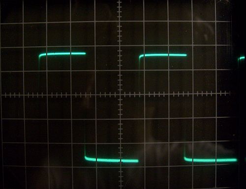
Below is with 1 KHz input and a load measured at 50 us/cm and 500 mV/cm showing the clean nature of the wave form. No overshooting, no ringing: |
|
| | | |
| |
 |
| | | |
| |
10 KHz Measurements |
|
| | | |
| |
Next, I measured the output of a 10 KHz, 2 V signal from the signal generator. I measured each channel, with no load, and with a 220 Ohm resistor on the output. |
|
| | | |
| |
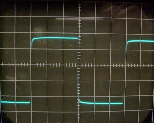
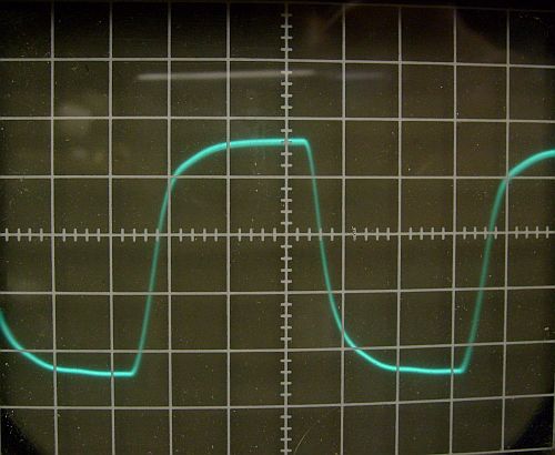
Below is with 10 KHz input and a load measured at 20 us/cm and 500 mV/cm: |
|
| | | |
| |
 |
| | | |
| |
As was true with the 1 KHz input, in every case, the result was the same. I could discern no difference between the response with a load or without. There was a slight difference between the output signal and the input signal shown here. The left edge of the top part of the wave is a bit rounded, and the right edge is a very sharp 90 degree angle. I guess that this reflects the limited high frequency bandwidth of the amplifier, and the sharp right edge is due to phase shift with the higher frequencies. |
|
| | | |
| |
Below is with 10 KHz input and a load measured at 5 us/cm and 500 mV/cm showing the clean nature of the wave form. No overshooting, no ringing: |
|
| | | |
| |
 |
| | | |
| |
Lastly, below is with 10 KHz input and a load measured at 0.5 us/cm and 500 mV/cm showing no suggestion of oscillation: |
|
| | | |
| |
 |
| | | |
| |
100 KHz Measurements |
|
| | | |
| |
Lastly, I measured the output of a 100 KHz, 2 V signal from the signal generator. I measured each channel, with no load, and with a 220 Ohm resistor on the output. |
|
| | | |
| |
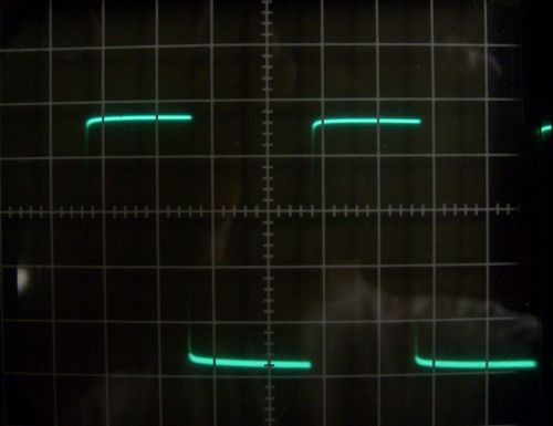
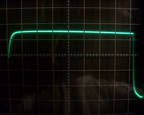
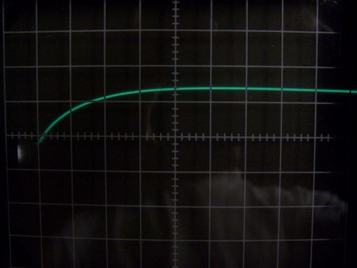
Below is with 100 KHz input and a load measured at 2 us/cm and 500 mV/cm: |
|
| | | |
| |
 |
| | | |
| |
As you can see, the 100 KHz output had some problems. Again, the limited high frequency range is causing rounding of the leading corner of the square wave. Considering that this is well out of audio range, I don't think this is a problem. At least the result didn't show any signs of stability problems. |
|
| | | |
| | | |