| |
 |
| | | |
| |
Introduction |
|
| | | |
| |
The preamplifier is a solid state device built around Rod Elliot's high-quality Project 88, Project 06, and Project 99 opamp-based preamplifier circuits. This is the second preamplifier that I have built. You can read about the first one here. The new one is much improved over the first, with better opamps (OPA627 instead of OPA2134), and a better power supply (AC mains filter, toroidal transformer, dual bridges with high-quality diodes, and dual high-quality regulators), and it sounds significantly better. |
|
| | | |
| |
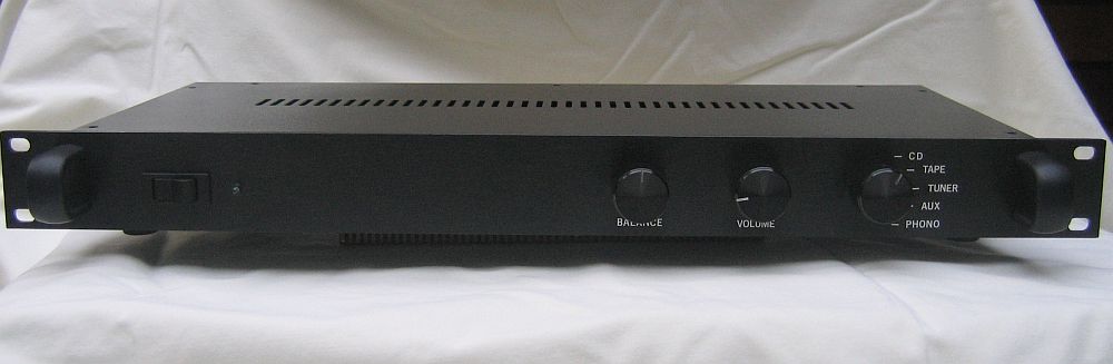
The preamplifier is housed in a 1U rack case. The front of the preamplifier has an on/off switch, a blue LED indicator light, a balance and volume control, and an input selector switch. |
|
| | | |
| |
 |
| | | |
| |
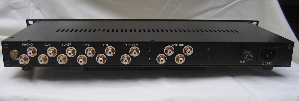
On the back, five sets of inputs are included, from left to right: Phono, Aux, Tuner, Tape Play, and CD. A set of Tape Out (record) jacks are included as well. Two identical sets of output jacks (Amp Out) are also provided. All of the inputs and outputs are gold-plated RCA jacks. |
|
| | | |
| |
Also on the back are a standard mains power connector and a 1 A fuse case on the right side, and a ground connector for the phonograph next to the Phono input jacks. |
|
| | | |
| |
 |
| | | |
| |
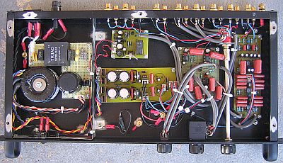
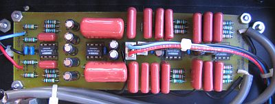
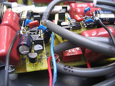
Inside the preamplifier case, the photo above shows the following, from left to right:- AC mains input, fuse, filter, and transformer
- Shield plate
- Output muting circuit board (top), power supply circuit board (middle), and floating star ground point (bottom)
- Preamplifier circuit board
- Input selector switch and aluminum shaft
- Phono circuit board
- Input and output RCA jacks on the back panel
- Power switch, balance control, volume control, and input selector switch on the front panel.
|
|
| | | |
| |
A Grayhill 6-position/2-pole rotary selector switch is used to control the inputs, and it is connected to the front-panel knob with an aluminum shaft. A high-quality Noble potentiometer is used for the volume control, and the balance control is a high-quality conductive-plastic pot. Both the volume and balance controls use a simple divider design and are not in the signal path. |
|
| | | |
| |
AC Mains Circuits |
|
| | | |
| |
 |
| | | |
| |
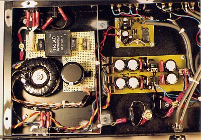
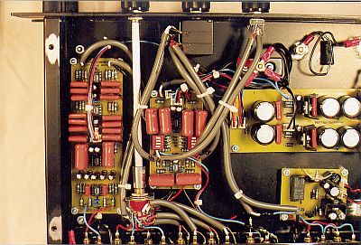
The hot AC mains lead is routed with 18 AWG stranded wire from the receptacle on the back panel (in the upper left corner of the above photo), to the front panel rocker switch, back through the 1 A fuse case on the back panel, and into the mains filter board. The ground from the receptacle is attached to a chassis ground point immediately to the left of the mains filter board, with a brass bolt, washer, and nut assembly, attached directly to the case bottom panel. |
|
| | | |
| |
The mains filter is built on a small, L-shaped piece of perf-board, and was designed to remove noise above about 27 KHz from the AC current. The filter uses two thin, yellow 130 VAC MOVs and two black, boxy, 100 nF X2/Y metallized film capacitors across the mains; two fat, yellow 2.2 nF Y2/X1 ceramic capacitors, one from hot to ground, and the other from neutral to ground; and two 470 KOhm resistors also across the mains. A 16 mH, 2.6 A, common-mode choke (the square, black box labeled TRIAD) is included in-line with both the hot and neutral lines to eliminate common-mode noise from the current. The large, low-voltage, high ripple-current, 12,000 uF electrolytic capacitor, protected by two opposite-oriented, high-current diodes, forms a "DC Trap" that eliminates an annoying 60 Hz buzz from the transformer that is caused by stray DC current in the AC mains. The ground wire from the filter is attached to the chassis ground bolt. |
|
| | | |
| |
The mains filter feeds a Plitron 15 VA toroidal transformer with two 15 VAC secondaries. The secondaries are routed separately to the power supply board's independent, dual rectifying circuits. The secondaries are not combined at this point to form the 0 V reference ground; the reference ground is created after the rectifying and smoothing circuits. |
|
| | | |
| |
The AC mains filter and transformer are isolated from the power supply board and the sensitive preamplifier and phono circuits by a galvanized steel shield. The shield is electrically connected to the top, sides, and bottom of the case, thereby creating a "Faraday Cage" that shunts any noise emitted by the AC components to the chassis ground so they do not effect the signal. |
|
| | | |
| |
Power Supply |
|
| | | |
| |
 |
| | | |
| |
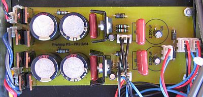
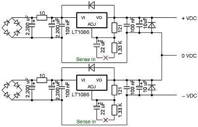
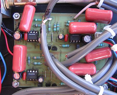
The power supply board, shown in the above photo, is a severely modified version of the ESP Project 05 power supply circuit. The schematic is shown below. Each secondary is rectified individually with a separate bridge, with each bridge consisting of four, OnSemi MSR860, 600 V, 8 A, soft-recovery diodes. Each bridge then feeds a separate regulator circuit composed of two 2,200 uF Panasonic FC series electrolytic caps separated by an in-line 10 ohm resistor, a 100 nF polypropylene cap, an LT-1086 variable voltage regulator, another 100 nF polypropylene cap, and a 10 uF FC series electrolytic cap. Protection diodes are included around the regulators, and resistors are used to constrain the regulators to 15 VDC. The (+) output of one of the regulators is combined with the (-) output of the other to form a common 0 VDC reference that connects to the star ground point. The other outputs from the two circuits form the +15 VDC and -15 VDC rails. Each board that uses the power supply has a "Kelvin sense" return wire that connects from the board's connection point to the circuit connected to the regulators' adjust pins to constantly adjust the regulation (shown by the X's in the schematic). As a result, the power supply board provides a very clean and very constant +/-15 VDC output. |
|
| | | |
| |
 |
| | | |
| |
Preamplifier Circuits |
|
| | | |
| |
 |
| | | |
| |
The combined RIAA phono circuit (ESP Project 06) and subsonic filter (Project 99) circuit board lies along the left side of the case and is shown in the above picture. The phono preamplifier (left half) uses OPA2134 opamps, and is utterly superb. It makes my old records sound as good as, and in many cases much better than, the CDs. The subsonic filter (right half) uses a bank of 150 nF caps and OPA2134 opamps to eliminate frequencies below 17 Hz. |
|
| | | |
| |
 |
| | | |
| |
The preamplifier board itself is shown in the above picture. The preamplifier receives the signal from the rotary switch and handles the volume and balance controls. The preamplifier has an imput impedence of 100 Kohm. |
|
| | | |
| |
The preamplifier board is based on the ESP Project 88 design. Originally, I made a single board for dual OPA2134 opamps that I later modified to accept OPA627 single opamps instead of dual opamps (as described here) . The new circuit layout is a side-by-side, dual-mono configuration with separate power and ground circuits and connections for each channel. The DIP switches were eliminated and the gain is set to 9 dB with a 10 Kohm resistor. |
|
| | | |
| |
Each side of the PCB contains two OPA627 opamps, and each opamp has an additonal circuit with two, cascaded 2N5457 JFET transistors and a 1.74 Kohm source resistor from the (-) power supply lead that supplies a constant 5 mA current to the opamp's output to "force" the opamps into class-A operation. There is also a small jumper before the output of each so the class-A circuit can be easily enabled or disabled. As described on the CD mod page, forcing the opamps into class-A brings out the best possible sound from the opamps. The cascaded JFET method is described, among other places, here. |
|
| | | |
| |
Each rail of each channel is bypassed on the PCB with 100 uF or 22 uF Panasonic FC electrolytic capacitors to ground within about 3 to 10 mm of the opamp supply pins. 100 nF ceramic capacitors are soldered to the leads of the electrolytic capacitors on the bottom of the board. 100 nF film capacitors are also on the PCB across the (+) and (-) rails as close to each opamp as possible. The ground connctions for the electrolytics are separate from the main circuit ground, and are connected together and run to the star ground point. |
|
| | | |
| |
Grounding |
|
| | | |
| |
A star-ground configuration is used. Signal grounds from the input jacks are collected for each channel at the rotary switch and run to the floating star point (located between the power supply board and the front panel), fed beneath the boards to keep the ground wires as close to the signal paths as possible. All power supply and ground wires are carefully bundled to prevent any open loops. Because the chassis is attached to the mains ground, the floating star point is not grounded to the chassis, and there is no perceptible hum in the output. |
|
| | | |
| |
The phono board and the preamplifier board each have two independent circuit grounds. The regular circuit grounds go from the boards to the star point, and the grounds from all rail bypass caps on the boards are kept separate from the circuit grounds, and are routed separately to the star point. The signal grounds are not connected to either board, but are routed directly beneath each board to the star ground point. All ground wires are tightly bundled with the power supply wires when possible to eliminate ground loops. |
|
| | | |
| |
Muting Circuit |
|
| | | |
| |
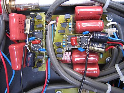
The output from the preamplifier board goes to a mute circuit near the output jacks, shown in both above photos. The mute circuit uses a direct AC feed from one of the transformer secondaries, and rectifies it to 12 VDC on the mute board. The DC is used to power the mute circuit, and to power the blue indicator light on the front panel, thereby keeping these circuits separate from the signal circuits. The mute circuit is an adaptation of the soft-start circuit originally published as ESP Project 39, before the circuit was modified for the pre-made PCBs. The circuit provides a half-second delay before energizing a small relay that connects the preamplifier output to the RCA output jacks. |
|
| | | |
| |
After the signal leaves the relay, it is split into two, and each split passes through a 100 ohm resistor before connecting to the RCA jacks. The 100 ohm resistors isolate the two outputs from the preamplifier circuit, and from each other, so the two amplifiers that are connected to the preamplifier can't "see" each other, and can't interfere with each other. |
|
| | | |
| |
Cables, Wires, and Connectors |
|
| | | |
| |
Internal wiring is 22 AWG hookup wire. Shielded cable between the input jacks and the selector switch, between the preamplifier and the volume and balance pots, and from the preamplifier to the mute circuit comes from decent-quality commercial interconnects. AC connections use Fast-On quick disconnects, or 9 A Molex Mini-Fit Junior plastic connectors with gold plated contacts. All DC power supply and ground connections use 3 A Molex-style plastic connectors with gold-plated contacts. All signal lead connections are soldered. |
|
| | | |
| |
Conclusion |
|
| | | |
| |
How does it sound? Extremely quiet and crystal clear. The highs are noticeably clearer and cleaner than in the first preamplifier. It really does sound like a "veil has been lifted". I think that the improved power supply and shielding really made a significant difference. Did the OPA627's make a diference? Did the dual-mono construction help? How about the class-A circuit? To be honest, I can't tell. But they didn't hurt! |
|
| | | |
| | | |
| |  | |
| | | |
| |
Modifications and Tweaks |
|
| | | |
| |
When I first built this preamplifier, I made the amplifier board in much the same way as the ESP Project 88 board, with a single circuit and dual OPA2134 opamps, as shown in the photo below. It sounded fantastic. |
|
| | | |
| |
 |
| | | |
| |
After a while, I wanted to make it better, so I decided to improve it by upgrading the two dual OPA2134 opamps to four single OPA627's. I was able to get more free samples from TI, just enough to replace the two OPA2134's. I removed the OPA2134's and replaced them with high-quality, gold-plated IC sockets. Then, I designed and built two daughter board adapters that plug into the sockets and hold the OPA627's. |
|
| | | |
| |
 |
| | | |
| |
Because of the large polypropylene capacitors used on the preamplifier board, the adapter boards had to be designed to fit the available space. The board used with the opamp for the input stage is wide and short, spanning the whole circuit board. The adapter board for the output stage had to be two-level in order to fit in the available space. These boards were pretty tricky to build. |
|
| | | |
| |
Each adapter board contains two OPA627 opamps. Each opamp has an additonal circuit with two, cascaded 2N5457 JFET transistors and a 845 ohm source resistor from the (-) power supply lead that supplies a constant 8 mA current to the opamp's output to "force" the opamps into class-A operation, like I describe above. |
|
| | | |
| |
 |
| | | |
| |
Finally, each opamp is bypassed with capacitors soldered directly to the power pins. A 100 nF polypropylene capacitor is soldered from the (+) to the (-) power pin of each opamp, and 100 uF electrolytic capacitors, paralleled with 100 nF ceramic capacitors, are soldered from each (+) pin to a ground wire, and from each (-) pin to a ground wire. The ground wires are connected together and run to the star ground point. |
|
| | | |
| |
Although I have a cassette tape deck that I sometimes listen to, I never record tapes anymore, for obvious reasons. So, I use the Tape Out jacks for the headphone amplifier. However, the Tape Out jacks take their feed from the selector switch, so the preamplifier does not need to be on when the headphone amplifier is used. This is not exactly true, however, because the preamplifier must be on to use the headphone amplifier with the turntable because the phono preamplifier requires power. There is always a catch! |
|
| | | |
| |
At any rate, I used this configuration for many months before I decided to make a new PCB with a layout to incorporate the single opamps, as described above. |
|
| | | |
| |
NOTE: In September of 2008, I replaced the preamplifier circuit with a FirstWatt B1 buffer preamplifier circuit, as well as redesigned the power supply. The B1 is a unity-gain, discrete buffer designed by the inimitable Nelson Pass with no capacitors in the signal path. You can read about it here. |
|
| | | |
| | | |
| |
Back |
|