| |
This page shows the results of testing the ESP P101 power amplifier (described here) with the borrowed oscilloscope (described here). |
|
| | | |
| |
Power Supply Measurements |
|
| | | |
| |
First, I measured the power supply, both the +42 VDC and -42 VDC rails. I measured the power supply with no input and no load (other than the amp boards, and the accessory boards themselves). |
|
| | | |
| |
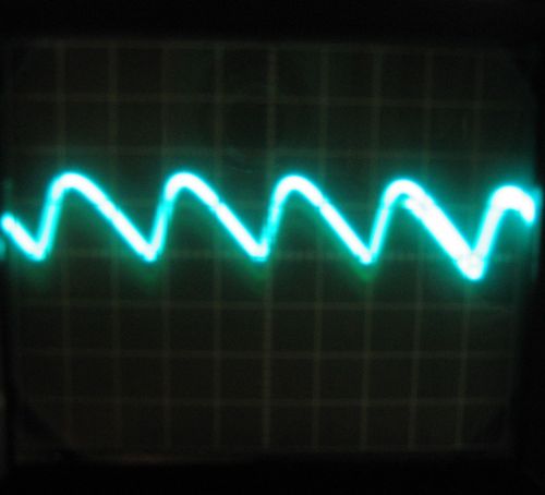
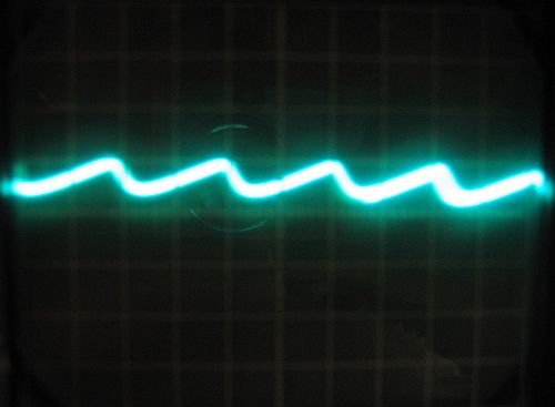
Because the power supply is unregulated, the signal showed a small amount of asymmetrical AC ripple at about 250 Hz. |
|
| | | |
| |
Below is the +42 VDC rail measured at 2 ms/cm and 10 mV/cm (the most sensitive voltage setting). The scope shows about 15 mV of ripple (about 0.04% of the supply voltage): |
|
| | | |
| |
 |
| | | |
| |
Below is the -42 VDC rail measured at 2 ms/cm and 10 mV/cm. The scope shows about 7 mV of ripple (about 0.02% of the supply voltage): |
|
| | | |
| |
 |
| | | |
| |
The first time I measured this, I found that the +42 VDC rail showed 22 mV of ripple, and the -42 VDC rail showed 11 mV. To try and reduce the amount of ripple, I inserted 0.1 Ohm, 5 W resistors in series on the two (+) traces of the smoothing circuit, midway between the four smoothing capacitors. This brought the +42 VDC rail ripple from 22 mV to 15 mV ( about a 32% decrease), and the -42 VDC rail ripple from 11 mV to 7 mV (about a 36% decrease). |
|
| | | |
| |
1 KHz Measurements |
|
| | | |
| |
Next, I measured the output of a 1 KHz, 0.5 V signal from the signal generator. I measured each channel, with no load, and with an old 8 Ohm speaker hooked up to the output. I used a four-foot piece of 14 gauge "zip" wire to connect it, and I put a 100 Ohm resistor in series with a 100 nF ceramic capacitor across the speaker terminals to terminate the cable and eliminate any high-frequency reflections. The 1 KHz and 10 KHz tones, even at 0.5 V volume, are quite loud and hard to take, so I wrapped the speaker in a blanket. |
|
| | | |
| |
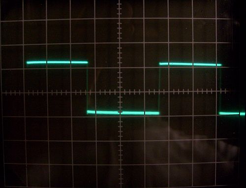
In every case, the result was the same. I could discern no difference between the response with a load or without. I couldn't really discern a difference between the output and the input signal shown here. Below is with 1 KHz input and no load measured at 0.2 ms/cm and 5 V/cm: |
|
| | | |
| |
 |
| | | |
| |
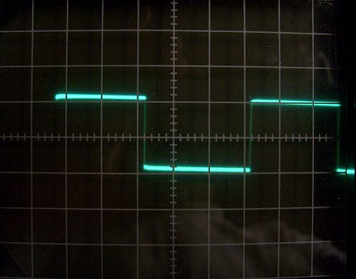
Below is 1 with KHz input and a load measured at 0.2 ms/cm and 5 V/cm. No difference: |
|
| | | |
| |
 |
| | | |
| |
You've got to admit, those responses are spectacular. |
|
| | | |
| |
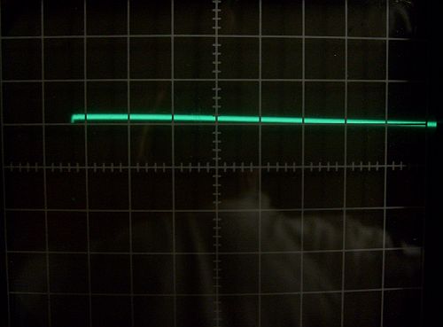
Below is with 1 KHz input and a load measured at 10 us/cm and 5 V/cm showing the clean nature of the wave form. No overshooting, no ringing: |
|
| | | |
| |
 |
| | | |
| |
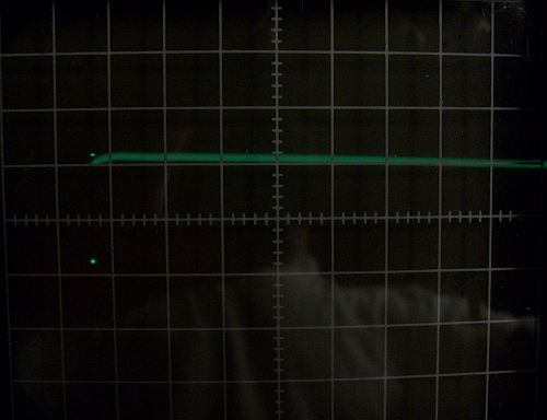
Below is with 1 KHz input and a load measured at 1 us/cm and 5 V/cm showing no sign of oscillation: |
|
| | | |
| |
 |
| | | |
| |
10 KHz Measurements |
|
| | | |
| |
Next, I measured the output of a 10 KHz, 0.5 V signal from the signal generator. I measured each channel, with no load, and with the 8 Ohm speaker on the output. |
|
| | | |
| |
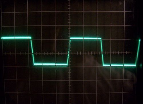
Below is with 10 KHz input and a load measured at 20 us/cm and 5 V/cm: |
|
| | | |
| |
 |
| | | |
| |
As was true with the 1 KHz wave, in every case, the result was the same. I could discern no difference between the response with a load or without. There was a slight difference between the output signal and the input signal shown here. The vertical parts of the wave here are a bit sloped (slowed "rise time"), indicating that the amplifier is slightly slow in reproducing the wave. |
|
| | | |
| |
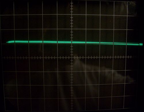
Below is with 10 KHz input and a load measured at 5 us/cm and 5 V/cm showing the clean nature of the wave form. No overshooting, no ringing: |
|
| | | |
| |
 |
| | | |
| |
100 KHz Measurements |
|
| | | |
| |
Lastly, I measured the output of a 100 KHz, 0.5 V signal from the signal generator. I measured each channel, with no load, and with the 8 Ohm speaker on the output. |
|
| | | |
| |
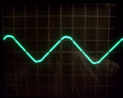
Below is with 100 KHz input and a load measured at 2 us/cm and 5 V/cm: |
|
| | | |
| |
 |
| | | |
| |
As you can see, because of the slower rise time, the 100 KHz wave is no longer square. I don't think this is a problem because the amplifier doesn't need to produce signals with this high of a frequency, and I think for stability reasons, this is normal. |
|
| | | |
| | | |


