| |
 |
| | | |
| |
Introduction |
|
| | | |
| |
For years I have been using the LM4562/BUF634-based portable headphone amplifier that I built (described here) to listen to music in my cube at work. It has worked well, and it sounds very good with my Sennheiser HD497s. But, I kept thinking about the huge sound improvement I got when I replaced my home-system opamp-based headphone amp with a Gilmore "Dynalo" discrete circuit, and the improvement when I replaced the home-system opamp-based preamplifier circuit with the Pass B1 discrete buffer. |
|
| | | |
| |
Now I wanted to replace the IC-based portable headphone amplifier with a better-sounding discrete design. |
|
| | | |
| |
I have another old OPA2134 opamp-based portable headphone amp (described here) that was one of the first things that I built, but it doesn't sound very good, and I never use it. I also have lots of leftover parts, so I decided to try and find a discrete amp to put in the old opamp-based amplifier box, using as many of my leftover parts as possible. |
|
| | | |
| |
The circuit I was looking for needed to be:
- A discrete design
- Highly regarded for quality
- Able to fit in the small (2.5 x 5.5 inches) project box
- Designed with components that I already have in my spare parts bin
|
|
| | | |
| |
I settled on a JLH variant that is discussed in this thread on the diyAudio forum. There is no question that the JLH class A discrete amplifier designs are very highly regarded. Because this variant uses a single rail from a single-sided power supply (+12 VDC/Ground), and a minimum number of parts, it had the best chance of fitting into the small enclosure. |
| | | |
| |
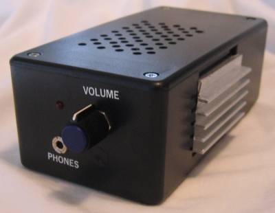
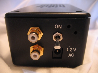
On the back of the case, you can see the AC power connection, the power switch, and the right and left RCA input jacks. |
|
| | | |
| |
 |
| | | |
| |
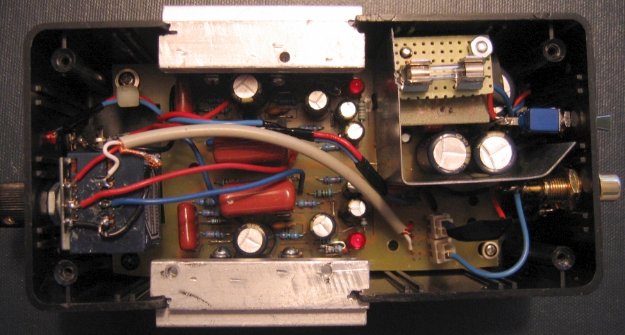
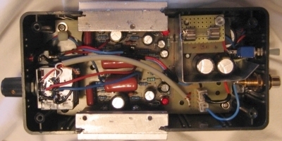
Inside the case, the photo below shows the amplifier and power supply on a single circuit board. The power supply is inside the little walled-off area in the upper right (back) corner, and the left and right amplifier circuits are side-by-side on the left (front) half of the board. Also visible are the heatsinks mounted in the sides of the case, and the internal wiring for the switches, LED, volume control, output jack, and input jacks. |
|
| | | |
| |
 |
| | | |
| |
Power Supply |
|
| | | |
| |
The power supply is fairly standard, and because it consists of only one side (+V/Ground), it takes up less room than a double-sided (+V/0/-V) supply. |
|
| | | |
| |
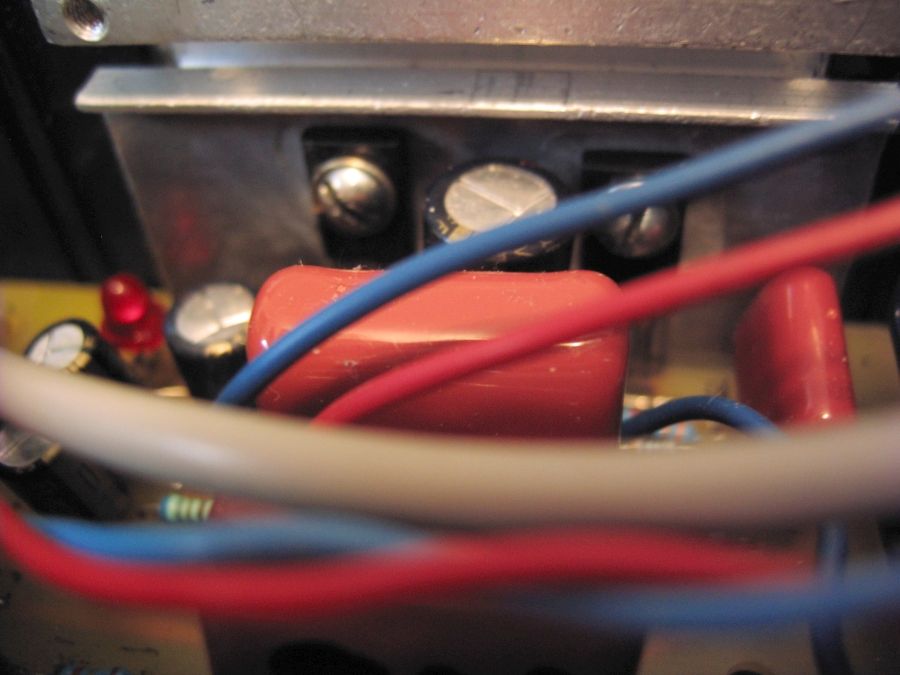
The AC comes from a 12 VAC, 1 A plug-in adapter that enters the case through a standard adapter plug on the back. The AC is routed through the switch on the back of the case, and then through the 750 mA fuse on the small board on the top of the stand-off above the main part of the power supply. The AC then feeds a rectifier bridge made up of four 1N4004 diodes on a small board directly under the fuse. |
|
| | | |
| |
The rectified voltage is then run through a 2200 uF smoothing capacitor, a 10 ohm resistor, and then two 1500 uF capacitors, for a total of 5200 uF of capacitance. |
|
| | | |
| |
The smoothed voltage is then run through a 100 nF film capacitor, and then through a LT1086 voltage regulator that uses a 121 ohm resistor and a 1 Kohm resistor to set the voltage to around 12 VDC. A 22 uF capacitor is used from the adjust pin of the regulator to ground. |
|
| | | |
| |
The regulated voltage then goes through a 100 nF film capacitor and a 10 uF capacitor before being fed to a single rail for the two amplifier circuits. The power supply supplies a steady 11.8 VDC. |
|
| | | |
| |
The entire power supply is separated from the rest of the circuitry inside the case with a thin metal shield that is connected to ground. The purpose of the shield is to intercept noise and radiated energy from the power supply (especially the diode bridge) so that it doesn't inject noise into the signal. |
| | | |
| |
Amplifier Circuits |
|
| | | |
| |
The input from the RCA jacks on the back of the case go to connectors on the amplifier board, then are immediately routed through a shielded cable to the volume potentiometer, then back to the amplifier circuits. The volume pot is a very good quality 50 Kohm Alps Blue that was originally used in my home preamplifier, but was replaced with a 25 Kohm Noble pot. |
| | | |
| |
The signal input from the volume control enters each amplifier circuit through a big 1 uF polypropylene capacitor, and a 100 Kohm resistor to ground set the input impedance. |
| | | |
| |
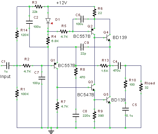
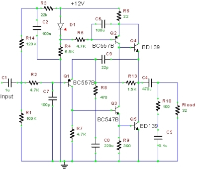
The schematic for this JLH variant is shown below. |
| | | |
| |
 |
| | | |
| |
For the small signal transistors I used BC550C and BC546C because those were the parts I had. I used BD139 for the output transistors as specified in the schematic. |
|
| | | |
| |
The BD139 transistors are mounted to the two heatsinks that are embedded in the sides of the case, so that the fins are exposed to the outside air, and not confined within the case (each heat sink has two transistors). |
|
| | | |
| |
 |
| | | |
| | | |
| |
All of the JLH amplifiers are class A, and this variant pulls a constant current of about 50 mA, so good heatsinks are required. These heatsinks are fairly stout (about 2.5 x 1.5 x 0.5 inches) and they get warm when the amplifier is playing. Not too hot to touch, but definitely warm (you can easily keep your fingers on them indefinitely). In fact, they measure 28 degC at idle, and between 32 and 35 degC when playing. I also drilled many holes in the top and bottom of the case to facilitate air flow within the case. |
|
| | | |
| |
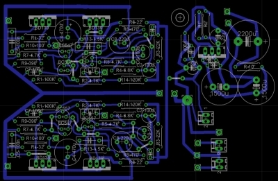
PCB Layout |
|
| | | |
| |
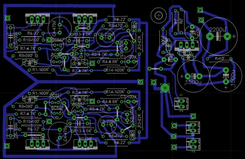
This design does not come with pre-made PCBs or even a circuit board layout. Basically, the schematic posted in the forum thread was about the only information I had to go on to create a PCB. In all of my past constructions, I created circuit board layouts only for simple projects, like power supplies or basic opamp circuits. For more complex circuits (such as discrete amplifiers), I used PCB layouts done by people much more competent than I. My layout for this project is shown below. I'm sure that it could be greatly improved on, but it was my best effort, and it seems to be working all right. |
|
| | | |
| |
 |
| | | |
| |
Conclusion |
|
| | | |
| |
First of all, I was amazed when it worked perfectly the first time I fired it up. I think that was a first for me. |
| | | |
| |
As for the sound, I am astounded at how good it sounds. Perfectly clear, open, airy. More power than I need. Dead quiet with the source off, no hiss, no hum; I cannot tell the difference between having the power switched on and switched off. The improvement was much more than I hoped for. The IC-based amplifier I was using before sounds so much darker and fuzzier by comparison. I highly recommend this little amplifier! |
| | | |
| |
A Minor Correction |
|
| | | |
| |
When I created the PCB layout and made the circuit board, I was careful to include every component that is shown on the schematic, unfortunately including the 32 Ohm "Rload" resistor shown at the output. |
| | | |
| |
Then I realized that the author was referring not to an actual resistor, but to the headphones themselves as the "Rload" resistor (headphones being typically 32 Ohms, and providing the load on the amplifier). To make matters worse, because the spurious 33 Ohm resister I added to the board for "Rload" is wired in paralell with the 100 Ohm resistor (R10), it reduced R10's effective value to about 25 Ohms. I have since removed the 33 Ohm "Rload" resistors from the two channels on the board. |
| | | |
| |
Additional Cooling |
|
| | | |
| |
Although the heatsinks do not get excessivly hot, they do get hot enough to make me want to cool them down a bit so that the amplifier lasts as long as possible. |
| | | |
| |
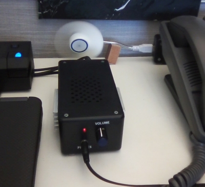
I bought a small, USB-powered fan for $8 on Amazon to place behind the amplifier box so that the breeze from the fan would gently and silently move the warm air away from the external heatsink fins towards the front of the box. |
| | | |
| |
 |
| | | |
| |
Unfortunately, the fan uses the full 5 VDC from the USB connection, and it spins very fast, makes a humming/buzzing noise, and it blows much harder than I need. So, I built a small switch box to go between the fan and the USB port on the laptop, to lower the voltage to an acceptable level. |
| | | |
| |
 |
| | | |
| |
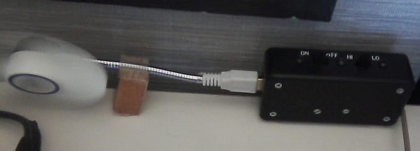
The switch box has a female USB connector (salvaged from a dead motherboard), a cable with a male USB connector to plug into the laptop, a power switch (the fan does not have one), and a switch to toggle between "high power" (about 2.6 VDC) and "low power" (about 2.4 VDC). |
| | | |
| |
The "high power" setting uses two parallel 47 Ohm resisters (for an effective 23.5 Ohms) on the power line. The resulting 2.4 VDC drop slows down the fan to just below where I can hear the fan noise. The "low power" setting uses a 50 Ohm and a 75 Ohm resistor in parallel (for an effective 30 Ohms), that drops the voltage by 2.6 VDC, just above the voltage where the fan won't start spinning on its own. The resistors for both settings have to dissipate only about one quarter (0.25) watt. |
| | | |
| |
The switch box is also weighted with about 5 ounces of Pinewood Derby car weights, so it stays put and does not fall over from the weight of the fan, or get blown around by the breeze. |
| | | |
| |
Does it work? Absolutely! The fins stay essentially cold to the touch with the fan running, way cooler than without the fan. The fan works much better than I ever imagined. Hopefully, this will make the poor little BD130 transistors last a lot longer than they would without the fan. |
| |
. |
| |
Back |
|