| |
 |
| | | |
| |
Introduction |
|
| | | |
| |
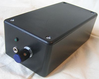
This portable headphone amplifier was originally built, as described here, with parts from my first home system. The poor thing was a horrible Frankenstein-like monster of various circuit boards bolted to each other with connecting wires running everywhere. Finally, it developed a nasty hiss after one of the BUF634's was bent back and forth too many times and one of the leads broke. Then I was left with no other choice but to rebuild it. |
|
| | | |
| |
As long as I was rebuilding it, I took the opportunity to improve things, such as:
- Increased the rail voltage to +/- 15 VDC
- Moved the crossfeed circuit from before the volume potentiometer to between the gain stage and the output stage
- Increased the capacitance in the power supply from 6,400 uF to 11,000 uF total.
|
|
| | | |
| |
 |
| | | |
| |
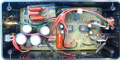
Inside the case, the photo above shows the amplifier and power supply now on a single circuit board, with the crossfeed board mounted above the power supply, and the internal wiring for all of the switches, LED, volume control, crossfeed board, input and output jacks. |
|
| | | |
| |
Power Supply |
|
| | | |
| |
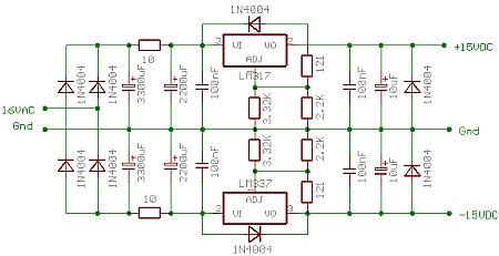
The power supply is a modified version of the ESP Project 5A as described here. I used all new parts, but I was still only able to fit one 3,300 uF and one 2,200 uF smoothing cap per rail. I also replaced the 100 uF caps downstream from the regulators with the 10 uF recommened by ESP. The schematic for the power supply is shown below. |
|
| | | |
| |
 |
| | | |
| |
The power supply is fed with a 16 VAC, 1.5 A external power pack, robbed from my first preamplifier, and it produces a clean, steady +/- 15 VDC. The incoming AC current is run first through a 0.5 A slow-blow fuse before feeding the rectifier diodes. The rectifier diodes are standard 1N4004 types. |
|
| | | |
| |
Headphone Amplifier Circuit |
|
| | | |
| |
The input from the RCA jacks go to connectors on the amplifier board, then are immediately routed through the super el-cheapo Radio Shack 100 Kohm, dual-gange audio volume potentiometer, then back to the amplifier circuit. |
|
| | | |
| |
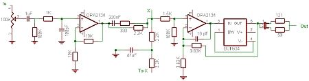
The amplifier circuit is basically the same one used in the original home hifi headphone amplifier described here. I removed the input stage so only two stages remain, the OPA2134 gain stage and the OPA2134/BUF634 output stage. The original schematic for one channel is shown below: |
|
| | | |
| |
 |
| | | |
| |
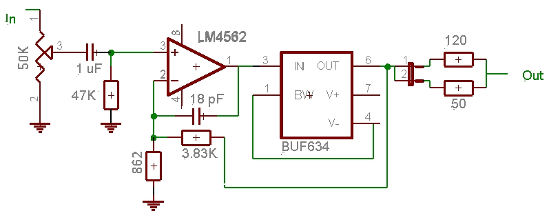
After messing around with the amp (as described here), I bypassed the first opamp circuit and removed the crossfeed circuit. The revised schematic for one channel is shown below: |
|
| | | |
| |
 |
| | | |
|
The signal input from the volume control enters the amplifier circuit through a 1 uF polypropylene capacitor, a 47 Kohm resistor to ground to set the input impedance, and a 1 Kohm serial resistor and 100 pF capacitor to ground to dampen oscillation. |
|
| | | |
| |
The gain stage is a very simple opamp gain circuit, and the output goes straight into the crossfeed circuit described in the following section. The gain stage is set to a voltage gain of 2X. (Note: this section has been bypassed). |
|
| | | |
| |
The buffered output stage uses an OPA2134 opamp (replaced with a LM4562) and two BUF634 buffers, and was originally built for the DAC. The circuit is based on a design by Pavel Macura. The output stage is fed by the crossfeed circuit described below, and is isolated from the previous stages with a 1.5 Kohm resistor. A 100 Kohm resistor to ground ensures a high imput impedance.(Note: these items have been bypassed). |
|
| | | |
| |
The output stage has a voltage gain of 2.7X. |
|
| | | |
| |
The buffers lower the output impedence so that headphones (30 to 300 ohms) can be driven, and the buffers are capable of providing considerably more current then the opamps alone. These features greatly improve the sound. A jumper on the output allows you to set the output impedance at either 50 or 120 ohms. |
|
| | | |
| |
The resistor and transistor networks used originally to "force the opamps into class-A" were removed. The BUF634 buffers are still run in class-A by connecting the BW pin to the (-) rail without a resistor. |
|
| | | |
| |
Crossfeed Circuit |
|
| | | |
| |
A bass-enhanced, natural crossfeed circuit is inserted between the gain stage and the output stage. The crossfeed circuit is described on the hifi headphone amplifier page, but here there is only one setting (approximately equivalent to the High setting on the hifi amplifier). The small, separate crossfeed circuit board is suspended above the upper part of the PCB on a 1" high standoff. The circuit is included in the amplifier schematic in the previous section. (Note: this section has been removed). |
|
| | | |
| |
Conclusion |
|
| | | |
| |
How does it sound? Excellent; no hum, no buzz, no hiss; dead quiet. The sound gives me goose bumps. It doesn't measure as well as the Gilmore headphone amp with the scope (as described here), but then, you wouldn't expect it to. |
|
| | | |
| |
As much as I hate to admit it, I think I am moved more by the music from this little amp playing MP3's through a sound card than I am through my Gilmore "Dynalo" home amp playing CD's with my modded CD player. This is probably due to the harmonic distortions that create "warmth" and "musicality", instead of the precise, clinical sound of no distortion. Interesting topic. |
|
| | | |
| |
Notes:
- In August, 2009, I replaced the two OPA2134 opamps with LM4562 opamps. Because the LM4562's have BJT front ends, instead of the FET front end like the OPA2134, the LM4562 can generate relatively high levels of DC offset if the currents at the + and - inputs are not balanced. I reduced the 100K Ohm resistor off the input to each opamp to 47K Ohms, and this reduced the DC offset to an acceptable value (about 8 mV). The LM4562 opamps sound clearer, with better bass than the "darker" sounding OPA2134. Although the amplifier no longer has OPA2134's in it, I am going to leave the page title the same for now (with quotes).
- In 2011 I mounted some serious heat sinks to the BUF634s, and I made some tiny wooden standoffs from dowels that I glued under the mega heat sinks. Now they are solid and stable, so I don't have to worry about movement causing the IC leads to eventually break.
- In April and August, 2011, I bypassed the first opamp stage and removed the crossfeed circuit.
- In 2016, I replaced the LM4562 opamps with the original OPA2134 opamps. I thnk they sound better. I didn't replace the 47 KOhm input impedence resistors with 100 KOhm resistors. I may do that someday, when I have it disassembled for some other reason.
- Also, I have pretty much replaced this amplifier with my new JLH class-A portable headphone amplifier, described here.
|
|
| | | |
| |
Back |
|