| |
 |
| | | |
| |
Introduction |
|
| | | |
| |
This headphone amplifier was built as a high-quality, opamp-based unit to be part of the main stereo system. I did not include a headphone amplifier in either the preamplifier or the power amplifier because a quality headphone amplifier is too large and complex to be put in with either of those components. So, I built a separate unit that can be used with any of my souces by plugging it into the preamplifier's Tape Out jacks, and using the preamplifier's selector switch. See the preamplifier page for details. |
|
| | | |
| |
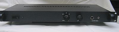
The headphone amplifier is a solid state device designed from various opamp-based circuits that are available on the web. It is housed in a 1U rack case, the final resting place of the DAC/Active Crossover case. The front of the amplifier has an on/off switch, blue LED indicator light, crossfeed selector switch, volume control, and two headphone jacks (a 1/4" and a 1/8" jack wired in parallel). |
|
| | | |
| |
 |
| | | |
| |
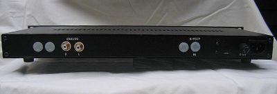
On the back are two gold-plated RCA input jacks on the left side, and a standard mains power connector and a 1 A fuse case on the right side. There are also several white hole plugs as a result of the case's previous service as a DAC and an Active Crossover unit. |
|
| | | |
| |
 |
| | | |
| |
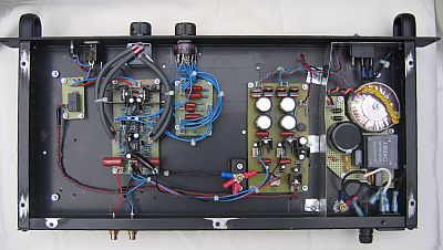
Inside the headphone amplifier case, the photo above shows the following, from right to left:- AC mains input, fuse, filter, transformer, and power switch
- Shield plate
- Power supply and muting circuit board, and adjacent floating star ground point
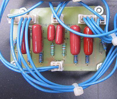
- Crossfeed circuit board with a selector switch on the front panel
- Amplifier circuit board with the input RCA jacks on the back panel and the volume control on the front panel
- Muting relay board and headphone jacks on the front panel
|
|
| | | |
| |
Power Supply |
|
| | | |
| |
The AC mains filter circuit, transformer, shield, and power supply board are identical to those used in the preamplifier. The muting circuit is also the same one used in the preamplifier, but here it is included on the power supply board. The relay is mounted on a separate board immediately behind the headphone jacks on the front panel. |
|
| | | |
| |
Headphone Amplifier Circuit |
|
| | | |
| |
 |
| | | |
| |
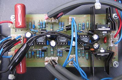
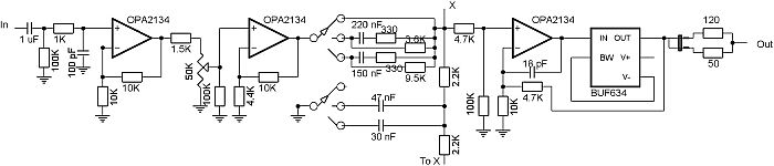
The amplifier incorporates an input stage, a buffered volume control, a gain stage, a bass-enhanced natural crossfeed circuit (described below), and a buffered output stage. The crossfeed circuit is built on a different board than the input, gain, and output buffers. All stages use OPA2134 opamps, and the output stage also uses the BUF634 buffers that were originally bought for the DAC. The shematic for one channel is shown below. |
|
| | | |
| |
 |
| | | |
| |
The input impedence is set at 100 Kohm with the resistor to ground. The 1 uF polypropylene input capacitor filters any DC that may be traveling with the input signal. |
|
| | | |
| |
The input stage has a gain of 2X, and acts as a buffer before the volume control. The volume pot is a 50 Kohm Alps Blue. The gain stage follows the volume control, with a gain of about 3X. |
|
| | | |
| |
 |
| | | |
| |
The signal is then sent through a 3-position, 3-deck rotary selector switch that controls the bass-enhanced natural crossfeed circuit. The crossfeed circuit that I used was developed by Jan Meier. Basically, the circuit takes a small part of each channel, delays it 0.3 seconds, and merges it with the other channel. This simulates the way you hear stereo speakers where the two speakers are located on either side of your head. The crossfeed moves the stereo image out from the center of your head and eliminates the high-powered sound that is otherwise blasted directly into your eardrums. It sounds more natural, and it really cuts down on the fatigue you normally get from listening to headphones for long periods of time. |
|
| | | |
| |
Two of the three decks on the selector switch are used to control the crossfeed level for each channel, and the third deck is used to control the common bass-enhancement part of the circuit that connects the 30 nF or 47 nF capacitor to ground. The three switch positions control the degree of crossfeed: Low, High, or Off (bypass). |
|
| | | |
| |
The buffered output stage uses an OPA2134 opamp and BUF634 buffers, and has a gain of about 0.75X. The buffers lower the output impedence so that headphones (30 to 300 ohms) can be driven. A jumper allows you to set the output impedence at either 120 or 50 ohms. |
|
| | | |
| |
All six of the opamp outputs are "forced" into class-A with a single 2N5457 JFET transistor and an 847 ohm source resistor between the (-) rail and the output. The single transistor method doesn't work as well as the cascaded dual method, but I ran out of transistors. Still, it works much better than just a resistor. See the preamplifier page for a discussion of opamps and class-A. The buffers are run in class-A by connecting the BW pin to the (-) rail without a resistor. |
|
| | | |
| |
Grounding |
|
| | | |
| |
A star-ground configuration is used. Signal grounds from the input jacks are collected and run to the floating star point (located next to the power supply board near the rear panel), fed beneath the boards to keep the ground wires as close to the signal paths as possible. Circuit grounds and bypass grounds are also run separately to the star point. All power supply and ground wires are carefully bundled to prevent any open loops. Because the chassis is attached to the mains ground, the floating star point is not grounded to the chassis, and there is no perceptible hum in the output. |
|
| | | |
| |
Cables, Wires, and Connectors |
|
| | | |
| |
Internal wiring is 22 AWG hookup wire. Shielded cable between the amplifier and the volume pot comes from decent-quality commercial interconnects. AC connections use Fast-On quick disconnects, or 9 A Molex Mini-Fit Junior plastic connectors with gold plated contacts. All DC power supply, signal, and ground connections use 3 A Molex-style plastic connectors with gold-plated contacts. |
|
| | | |
| |
Conclusion |
|
| | | |
| |
How does it sound? Well, because I don't have a high-end set of headphones to test it with (yet), I can't be sure how good it its. But, it sure sounds wonderful with my Senheiser HD497 headphones that I use with my portable headphone amplifier. The crossfeed circuit is especially nice, although there doesn't appear to be much difference between Lo and High. With any luck, Santa will bring me a new pair of Sennheiser 580's and I will then be able to judge how good this amplifier is. |
|
| | | |
| |
NOTE: In early 2006, the OPA2134/BUF634 amplifier board was replaced with a Gilmore "Dynalo" discrete class-A amplifier, as described here, and the OPA2134/BUF634 amplifier was incorporated into a new portable headphone amplifier as described here. The power supply, crossfeed, and output relay boards were kept in the box and used with the Gilmore amp. |
|
| | | |
| |
Back |
|