 |
||
| Introduction | ||
| Ever since I read the biamping article on the ESP web site I have wanted to try my luck at it. Biamping is the technique of using individual amplifiers to drive the woofers and tweeters separately. The signal from the preamplifier is split with an active (line-level) crossover circuit that sends the high (tweeter) and low (woofer) signals to the two amplifiers. The active crossover takes the place of the passive crossover networks in the speaker boxes themselves. For the many reasons discussed in the ESP article, biamping has the potential to make speakers sound far better than they can with passive crossovers. | ||
| With the completion of the second P3A amplifier, I now have two roughly equal amplifiers that I can use for biamping. As I describe on the Speakers page, I built the second set of AR.COM speakers with four-way binding posts so the internal crossovers could be bypassed, and the woofers and tweeters connected separately. My plan was to build a prototype, hand-programmable active crossover to find the optimum settings, then build a hard-wired crossover of comparable quality to the rest of the system and use both amplifiers to power my system. | ||
| Prototype Crossover | ||
| The prototype active crossover that I built is known as the "MOX" crossover because it was designed by the DIYAudio member who goes by the screen name of "Moamps". For each high-pass and low-pass section, the MOX crossover allows you to vary the filter order (6 dB/octave first order, 12 dB/octave second order, etc), the crossover frequency, the Q (slope), and the output volume. The MOX crossover is described in several threads about it in the DIYAudio Solid State forum. | ||
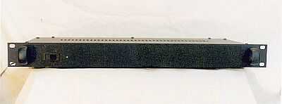
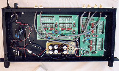
| Below is a photo of the MOX crossover that I built. I added a baffle-step compensation circuit to the low-pass outputs as described here. I borrowed the DAC case and used the transformer pack and P05 power supply from the first preamplifier to power it. | ||
 |
||
The first step in finding the optimum crossover settings is to determine what the parameters of the existing passive crossover are. I tried my best to reverse-engineer the AR.COM crossover, but that was easier said than done. I knew that the approximate crossover frequency was 3 KHz, but calculations using the values of the capacitors and inductors in the crossover do not make this obvious. I substituted resistors in the MOX crossover's frequency array to more closely bracket the 3 KHz value, and as a starting point I set all of the filter circuits with the following values:
|
||
| The first thing I noticed was that the treble was way too loud. I ended up turning down the high-pass output by half. I continued to experiment with various settings on the crossover. | ||
| Results | ||
| Well, I have to admit that I could not get the speakers to sound as good as they do with the passive crossover. I came close, but the speakers always sounded flat and lifeless, lacking the spaciousness that the original crossovers provided. Eventually I gave up. | ||
| Conclusions | ||
| Ed Frias warned us in a post on the DIY Speaker Forum that biamping would be very difficult with these speakers. The AR.COMs sound as good as they do because of the crossover that Ed so artfully crafted, and this is not something that is easily replicated with an active crossover circuit. And he is obviously right. | ||
| I think I have confirmed here that making speakers sound good is clearly an art. Science might get you started, but to craft excellent sounding speakers requires talent, experience, etc. etc. (you can buy fancy paints and brushes and read lots of painting books, but you won't be able to improve on the Mona Lisa). I guess I knew this all along, but I wanted to see for myself. And I did. | ||
Back