| |
 |
| | | |
| |
The power amplifier is a solid state device based on the ESP Project 3A (P3A) amplifier, a highly regarded design in the DIY HiFi community. |
|
| | | |
| |
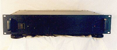
The P3A board was cut in half to separate the two amplifier channels, and each has its own power supply. Except for the shared transformer, it is a true "dual mono" design. The amplifier is housed in a 2U rack case. The only features on the front of the amplifier are the on/off switch, a green LED indicator light, and a red LED clipping indicator light. |
|
| | | |
| |
 |
| | | |
| |
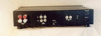
The back of the amplifier has two preamplifier-in RCA jack inputs, and four, 5-way, speaker-out terminals. All input/output jacks are gold-plated. The AC input receptacle and a 6 A circuit breaker are also seen on the far right of the above photo. Another set of four RCA jacks allow you to route the subwoofer input cables through the amplifier's relays to take advantage of the muting function of the DC protection circuit (described below). Also found on the back of the amplifier, is the jack for a 12 VDC external power pack that runs the fan controller circuit. This circuit is not switched, so it will continue to run after the amplifier is switched off, if necessary. |
|
| | | |
| |
 |
| | | |
| |
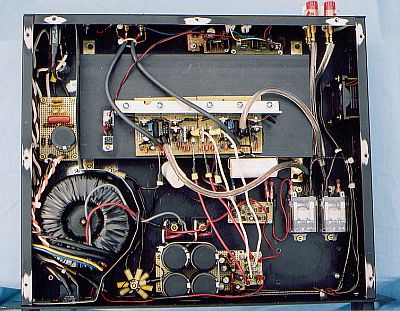
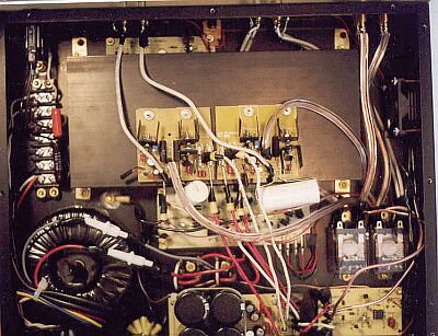
Inside the amplifier case you can see the heat sink with the amplifier boards on it, the AC-in terminal block in the upper left corner, the transformer and power supply along the bottom, the cooling fan in the upper right, the DC protection unit and relays, and the clipping indicator in the lower right corner. |
|
| | | |
| |
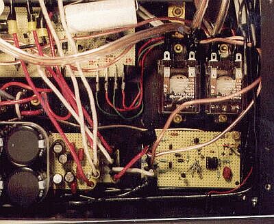
The amplifier uses a single star-grounding scheme. The floating star point can be seen at the bottom of the photo below. The ground wires from each board, as well as the negative speaker terminals and the power supply cap grounds, are collected at the star point. A single cable then connects the star point to the chassis at a point between the transformer and the heat sink. Input signal grounds are connected to the amplifier boards via shielded cable. |
|
| | | |
| |
 |
| | | |
| |
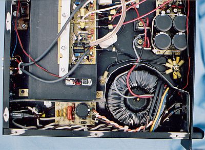
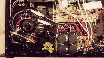
The Plitron 400 VA transformer takes up the lower left quarter of the amplifier case, and contributes about half the weight (the other half comes from the heat sink). |
|
| | | |
| |
The power supply is actually two independent power supplies (one for each amplifier/channel) that share the one transformer. The secondaries from the transformer (protected by in-line 5 A slow-blow fuses) are split and fed to two 35 A bridge rectifiers that are bolted to the chassis. The DC output from the bridges are fed to two, parallel, independent smoothing circuits with one 10,000 uF Panasonic (TSHA series) 105 degree, electrolytic capacitor per rail (40,000 uF total). The resulting DC current is further smoothed with electrolytic and film caps before being fed to the boards. Each of the supplies produces +/- 43.7 VDC unloaded, and about +/- 42 VDC loaded. All DC power leads to the boards, as well as ground cables, are 12 AWG solid copper wires. |
|
| | | |
| |
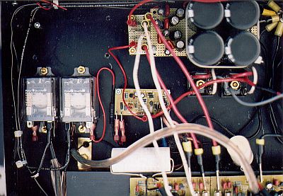
Above the power supply in the picture is the DC speaker protection/muting circuit. This circuit (ESP Project 33) protects the speakers in case of an amplifier fault by switching off the relays (and thereby cutting off the amplifier output to the speaker terminals) when appreciable DC current is detected in the output. The input is suppled from two 14 AWG wires that split from the amplifier output wires. Failure of the output transistors can send the full rail voltage (42 VDC) to the amplifier output, which is more than enough to destroy the speakers. The circuit also has a 1 to 2 second delay on turn-on before the relays are energized, and it disconnects the relays instantly when the amplifier is turned off. This keeps the pops and thumps from the amplifier turn on/turn off from going out to the speakers. |
|
| | | |
| |
The DC protection board shown in the picture was hand-built from the schematic. It has since been replaced with a (very much smaller!) professional board sold by Rod Elliot that didn't become available until after the amplifier was finished. |
|
| | | |
| |
 |
| | | |
| |
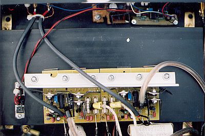
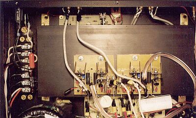
The two P3A amplifier boards are shown in the photo above attached to the head sink. Lying flat, the heat sink is not in the ideal orientation for cooling, but since it is quite large, and is cooled (when necessary) by an automatic temperature-controlled fan, the transistors and the heat sink only get warm to the touch when the amplifier is pushed fairly hard. The bottom plate of the case is perforated beneath the heat sink to add ventilation. The fan control circuit (ESP Project 42) can be seen just above the heat sink, with a small heat sink on the switching transistor. |
|
| | | |
| |
Note the very large, white, 10 uF polypropylene input capacitors (C1) on each amplifier board. The miller caps (C4 and C6) are 600V polystyrene. The input cable is the shielded Teflon cable discussed on the Cable and Wire page. The wire from the amplifier output through the relays to the speaker-out terminals is 12 AWG stranded copper ("zip") wire. |
|
| | | |
| |
Also shown in the photo above is the terminal block wiring that handles the AC input. The AC is routed from the receptacle to the front panel high-inrush rocker switch, through the 6 A circuit breaker, and on to the transformer. All wiring uses 14 AWG solid copper wires taken from Romex cable. The AC ground is attached to the chassis right at the AC receptacle. The AC mains are bypassed with a 100 ohm - 100 nF RC network to eliminate any high-frequency signal. |
|
| | | |
| |
Since these pictures were taken, I have also added a "DC Trap" on the mains wiring, consisting of two 22,000 uF, low-voltage, high ripple-current electrolytic caps, protected by two opposite-oriented, high-current diodes, as well as a MOV across the mains leads for surge protection. This "trap"was necessary to stop an annoying 60 Hz buzz from the transformer that was caused by stray DC current in the AC mains. |
|
| | | |
| |
 |
| | | |
| |
The circuit board in the lower right corner of the above photo is a clipping indicator (ESP Project 23). It is designed to turn on the little red LED when the output gets within 3% of clipping. The inputs come from two 14 AWG wires that split off the speaker-out wires. I am not sure that this circuit really works, because I have never been able to take the pressure levels above half volume. Maybe when my sons become teenagers I will find out if it works. |
|
| | | |
| |
Also shown in the above photo are the two relays that are controlled by the DC protection/muting board. They are sealed, industrial-strength relays that are probably overkill for this application. When they click on, you hear it! |
|
| | | |
| |
In order to keep as much circuitry as possible out of the signal path, the amplifier has no short-circuit or thermal protection. The DC protection circuit protects the speakers in the event of an amplifier fault, but it does not protect the amplifier itself. Shorting the input jacks or the speaker-out jacks (by plugging or unplugging cables while the amplifier is turned on, for example), will literally blow-up the amplifier. The fan will attempt to cool the amplifiers if they get too hot, but there is no circuit to shut the amplifier off if it gets too hot. |
|
| | | |
| |
So, how much did it all cost? The total cost for the initial construction of the amplifier and preamplifier together was about $1,100. However, following the initial construction, I went through a several-month nightmare of testing, destroying, repairing, destruction and repairing again that added several hundred dollars to the cost. I'm ashamed to say that most of the problems were self inflicted, while I learned the hard way how to be careful. |
|
| | | |
| |
And finally, how does it sound? Utterly superb! What a difference "no distortion" makes! I now understand what is meant by the terms "open" and "airy". Each instrument becomes clear and separate. And, the amplifier is dead quiet. If you turn off the source, turn up the volume full blast and put your ear right up to a speaker, you will swear that the amplifier is turned off. No hint of any noise. In terms of quality, many of the audiophile DIY folks say that the P3A is as good an amplifier as they have ever heard of this kind (A/B) at any price. My guess is that you would have to spend somewhere around $2,000 to $3,000 to get the same sound quality. |
|
| | | |