 |
 |
 |
|
|
|
| These pages showcase the stereo HiFi system that I began building in early 2002. I have been lusting after an audiophile-quality stereo since I was about 12 years old, but I could never afford one. Now, with the advent of the internet, it has become possible to learn enough to actually build very high-quality audio gear at much less than the cost of commercial offerings. Of course, it turned out to be a lot harder than I had thought, but with much research, study, perseverance, hard work, and a lot of outside help, my dream finally came true (click here to see how this all happened, and click here to see a chronologic history of my hobby). | ||
| Introduction | ||
| Actually, these pages describe my second round of HiFi construction. I originally built a preamplifier, amplifier, DAC, bookshelf speakers, and subwoofer system during 2002. As I continued to learn more about high-end DIY audio construction, I soon realized that I could build a much better system with what I had learned building the first one, and with what I have learned since. So, in about mid 2003, I began the second round of DIY HiFi construction detailed below. | ||
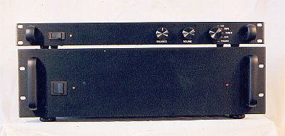
| I realized that I could improve the preamplifier and amplifier primarily in two ways: bigger and better power supplies, and better noise reduction and protection. As a result, I added to the power supplies AC mains filters; independent dual bridge rectifiers; ultra-fast, soft-recovery rectifier diodes; bigger capacitor banks; and bigger transformers. I also added shielding, better grounding practices, and better wire management to reduce noise. I made real PCBs instead of using perf-board for some of the auxiliary circuits. Otherwise, the preamplifier and amplifier circuit designs and component quality are about the same in the second round as in the first. | ||
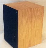
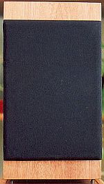
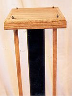
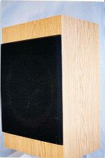
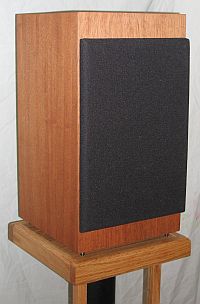
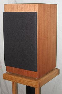
| I also had a second set of AR.COM speaker drivers that I was using in rough, painted, MDF boxes that I had made originally, and I wanted to build a nicer set of cabinets for them. I also wanted to wire them so I could try "biamping" the speakers with both amplifiers. Biamping uses individual amplifiers to drive the two woofers and two tweeters separately with an active crossover network, in place of the passive crossover networks in the speaker boxes themselves. An excellent discussion on the subject is found here. Including the existing subwoofer, I would actually be building a "triamped" system, with the active crossover splitting the preamplifier signal three ways (to the subwoofer, the woofers, and the tweeters). The plan was to use a prototype, hand-programmable active crossover to find the optimum settings, then build a hard-wired crossover of comparable quality to the rest of the system. See the Active Crossover page for details (hint: it didn't really work out too well). | ||
| I'm still tweaking things a bit, but for the most part I finished this project in late 2005. After building two amps, two preamps, two sets of speakers, and lots of accessory stuff like the headphone amps, CD player mods, and custom cables, I can no longer justify spending the money to build anything more. Mostly, I've worked just on my various headphone amplifiers over the past several years. | ||
| Another reason I haven't been building much anymore is that many of the "through the hole" parts (such as capacitors and resistors) are not being manufactured anymore, and will eventually go away. They are being replaced by the minaturized "SMD" parts, and I am not skilled at soldering those timy little connectors. Also, it is nearry impossible to get the critical transistors that many of the DIY circuits require. | ||
| My system now sounds as good as I am able to make it, so it is time now to just sit back and enjoy it. | ||
| DIY HiFi Component Pages | ||
| Please peruse the following pages for photos and detailed descriptions of the various components I built or upgraded during the Second Round. You can click on most of the photos to see larger versions. If you have any questions or comments, please send me an email at . | ||
| About My Adventure | ||
| How This All Happened: | ||
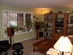
| I got started in this hobby gradually. What happened was, I wanted to record myself playing the guitar (for my kids) so I set up a cheap digital recording studio in my house, with a cheap, digital sound card (Hoontech XG), some cheap, old, PZM microphones (Crown Soundgrabbers), and a limited-shareware version of CoolEdit 96. I found a ton of good information on the internet about recording at home on the cheap. I made a simple microphone mixer, made a guitar pickup for a couple of bucks in parts, and tried to build a microphone preamplifier from a kit (with limited success). I soon realized that what I really needed was some decent speakers ("near-field monitors") to replace the super-cheapo computer speakers so I could do post-processing on the digital files. I searched the web for a design I could build, and, among others, ran across the AR.COMs. The reviews were so stellar that I ordered the parts, and built some crappy painted MDF boxes. Then, I hooked them up to my living-room stereo to see how they sounded. I was blown away at how much better they sounded than the old Cerwin Vega speakers I had been using as my livingroom stereo speakers. I quickly forgot about the recording studio and began building some nice, high-WAF cabinets for the speakers so they could stay in the living room. | ||
| After building the speakers, I started looking around the web and decided that there just might be enough practical information out there to make it possible to actually build high-quality HiFi electronic components. I have no formal electronics training, and electricity has always mystified me, so I checked out a big, fat book on Electronics Theory from my local library and read it cover to cover. I learned about resistors, capacitors, inductors, diodes, transistors, Ohm's law, and how circuits work when you combine the various components. I read everything I could find on the internet, and as much of the ESP web site as I could (there is a lot!). Also, there are lots of web sites like this one that describe other people's DIY journeys. As I began to figure things out, I started reading the posts on the DIYAudio solid-state message board (my screen name: "saurus"). There is an incredible amount of theoretical and practical information in those posts, many from professional electrical engineers, audio electronics designers, very experienced DIY builders, and even some of the pioneers who invented high-end audio, such as John Curl, Bob Cordell, Nelson Pass, Walt Jung, and Charles Hanson. They share whole lifetimes of accumulated knowledge and practical experience - where else can you get that? And, you can post specific questions when you get stuck, and they will cheerfully offer help. There are also some not-so-expert people offering well-intentioned but bad information, but you can sort it out. Without ESP and the DIYAudio sites, I never could have pulled this off, and I never would have tried. | ||
| By the way, I still haven't gotten around to making those guitar recordings yet. | ||
| Making Printed Circuit Boards: | ||
| My first round of construction used circuit boards bought from Rod Elliot on his ESP web site, or were hand-wired on pieces of perf-board. For the Second Round, I made some modifications to the amplifier, preamplifier, phono, and subsonic filter board layouts to suit my application, and then made the PCBs myself. I also designed and made PCBs for other components for which ESP does not sell boards, such as my active crossover, DAC output buffer, line-level power supplies, fan controllers, mute circuits, and the amplifier clipping indicator. I made the soft-start boards before they came available to buy on the ESP site. | ||
| To make the PCBs, I used the Eagle version 4.09r2 software program to design the circuits and create the layouts. I then printed the bottom (normal) and top (reversed) "silkscreen" patterns with a laser printer onto glossy paper and ironed them onto the copper-coated circuit boards. I used ferric chloride to etch the copper coating, then scrubbed the boards and hand-tinned the tracks. I used 1/19" and 1/24" bits to drill the holes. Numerous variations of this method are described on the web, such as here. | ||
| Before you send me a scathing email, let me say that I have purchased lots of boards from ESP, including a P05, a P06, two P88s, a P09, a P33, and six P3A boards. I only made boards for projects that I needed to modify, or for which there are no boards to buy. I am a strong supporter of the ESP site. Rod's designs are absolutely top notch, his prices are reasonable, his documentation is extensive and very helpful, and his support is superb. | ||
| For higher-powered circuits, such as AC mains filters, power amplifier rectifiers and DC smoothing, I did not make PCBs. Instead, I used perf-boards with hefty 12 to 18 AWG solid copper wires soldered to the component leads on the undersides of the boards. I did not want to take the chance of a PCB trace burning through from excess current. | ||
| Where I Got All the Stuff: | ||
| Electronic components were purchased on-line from DigiKey and Mouser. All 1/4 and 1/2 watt resistors are 1% metal foil, and film capacitors are polypropylene or polystyrene in the signal path, with some film and ceramics for bypassing. Electrolytic caps are Panasonic FC series, unless otherwise noted. Bourns trimmer pots were used. Transistors were purchased from Newark Electronics, or obtained directly as samples from OnSemi. The DAC IC's were purchased from AudioChips.net (now defunct). | ||
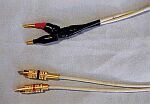
| Hookup wire is stranded copper 22 AWG. Shielded wire came from decent-quality, commercially-available interconnects. Amplifier output wire is 12 AWG stranded copper ("zip") wire. The amplifier, preamplifier, active crossover, and DAC cases are ParMetal 19" steel rack cases with 1/8" anodized aluminum front plates. Modifications to the cases were done with a power drill and a saber saw. Heat sinks were purchased on Ebay. Tools and supplies came from CircuitSpecialists (very cheap!). PCB supplies came from You Do It Electronics Center in Needham, MA (I live in the Boston area). Miscellaneous electronics supplies, such as desoldering braid, fuses, etc., were procured from Radio Shack. | ||
| Speaker drivers were purchased from Madisound, and crossover parts were ordered from MCM Electronics. Speaker accessories came from PartsExpress, and Meniscus Audio. Veneer for the speakers came from Constantines Wood Center. Speaker cabinet and speaker stand materials came from Home Depot, and other assorted hardware stores. | ||