| |
 |
| | | |
| |
Introduction |
|
| | | |
| |
After listening for a while to the preamplifier, amplifier, speakers, and subwoofer from the first round of construction, I realized that my cheap-o POS Japanese mass-market mid-fi CD player just wasn't cutting it anymore. I sure couldn't afford a new, audiophile-quality CD player, and it's not practical to make one. This left buying a used one as the only option - hellooo eBay! |
|
| | | |
| |
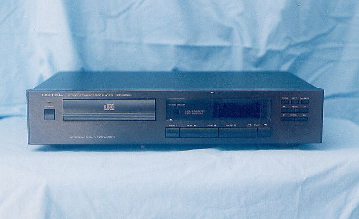
After much internet research, I came to the conclusion that the best option for decent quality, affordable price, and durability in a used machine, is the Rotel brand. Not the highest of HiFi, but respectable. After months of watching and bidding, I finally got a 1992 RCD965BX, complete with remote, for $150. Not bad, considering it retailed for about $600 new 12 years ago. The previous owner claimed it had been stored for many years, and when I got it, I opened it up to clean it and service the laser, and it was absolutely spic and span inside - like new! It clearly has very low miles on it. I was very lucky. |
|
| | | |
| |
Now that I had an old, but decent quality, machine, I investigated how I could upgrade it ("tweak it" in DIY-speak) to make it better. Many tweaks that people advocate seem pointless, of marginal value, silly, or even downright foolish or dangerous, but I did decide to make three modifications that appeared to be worthwhile:
- Replace the analog output stage opamps with newer, better ones
- Add a re-clocking circuit
- Add an AC mains filter
With much trepidation, I purchased a copy of the machine's Service Guide on-line, and carefully dismantled the unit. |
|
| | | |
| |
Opamp Upgrade |
|
| | | |
| |
The opamp upgrade involved replacing the two opamps in the output buffer with newer ones, and bypassing the opamp power rails. The opamps that were in it (NE-5534's) were state-of-the-art 12 years ago, and are actually very good, but there have been advances in opamp construction since then. I opted to go with OPA627 opamps as replacements, and Texas Instruments was kind enough to send me three as free samples (they cost $15 each to buy). |
|
| | | |
| |
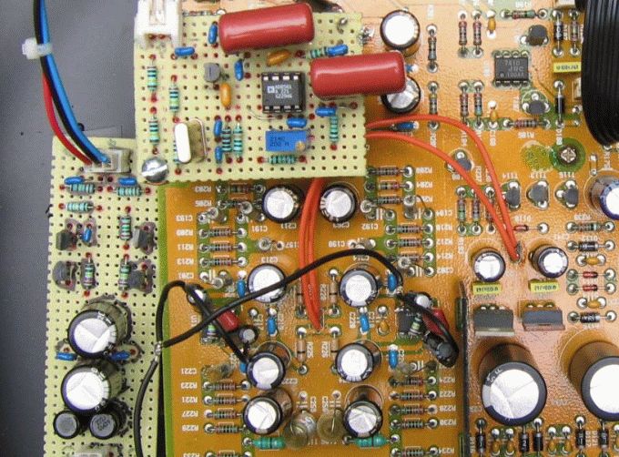
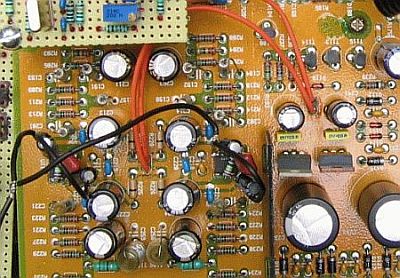
The opamps are located on the tan colored circuit board near the arching red wire (beneath the black wires), as shown in the photo below (the two tiny, rectangular black objects with eight little silver pins, four on each side). In order to desolder the old ones and resolder in the new ones, I had to remove the wires and detach the main circuit board from the case and turn it over. |
|
| | | |
| |
 |
| | | |
| |
Originally, I bypassed each opamp rail to ground with 100 pF ceramic capacitors soldered right to the power pins of the opamps on the underside of the PCB, and ran the ground wire to the ground lug on the PCB corner screw shown in the photos below. After reading as much as I could find about using the OPA627 for audio, I also attached 22 uF electrolytic capacitors from each power rail pin to ground, as well as a 100 nF film capacitor between the rail pins on each opamp. I soldered these directly to the pins on the top side of the PCB, as shown in the above photo. I ran the ground wire to the same ground lug on the PCB screw. When I returned to this project to re-do the class-A wiring (see next paragraph), I removed all of the bypass capacitors described above, and replaced them with 100 uF electrolytic and 100 nF ceramic capacitors from the (+) and (-) power pins to ground wires, and 100 nF polypropylene capacitors across the (+) and (-) power pins, exactly as described for the preamplifier. |
|
| | | |
| |
Also, I originally attached resistors from the output pins to the (-) power rail pins of each opamp in order to "force" the opamps into class-A operation. Forcing the opamps into class-A brings out the best possible sound from the opamps, and the various ways to accomplish this are discussed here. The preamplifier that the CD player feeds has an imput impedence of 100 Kohms, and the CD player has a maximum output of 2 VDC, therefore a maximum current of I = V / R = .02 mA can be drawn through the opamps by the preamplifier. A 26.7 Kohm resister from the -15 VDC rail and the opamp output is in parallel with the 100 Kohm load, thereby giving a total of 21.1 Kohms. Assuming a +/-15 VDC supply, the 26.7 Kohm resistor forces 0.71 mA through the opamps, which is more than 35 times the maximum needed current to provide class A at all times, and more than 60 times less than the 45 mA maximum current the opamp can deliver, thereby ensuring that they don't overheat. | |
| | | |
| |
However, after upgrading the preamplifier with OPA627 opamps and using dual, cascaded 2N5457 JFET transistors with 847 ohm source resistors to force class-A operation with 1 mA, I came back and did the same here. The cascaded transistor method provides a much steadier current than a simple resistor. I soldered the two transistors and the resistor together for each opamp, then soldered these directly to the (-) power pins and the output pins. | |
| | | |
| |
Re-Clocking Upgrade |
|
| | | |
| |
 |
| | | |
| |
Re-clocking involves adding a new circuit board that fine-tunes the output from the CD player's internal clock crystal so that the digital-to-analog wave reconstruction is a little cleaner. This minimizes the noise (called "jitter") that degrades the sound. You can buy pre-made clock circuits, but I decided to build my own. |
|
| | | |
| |
 |
| | | |
| |
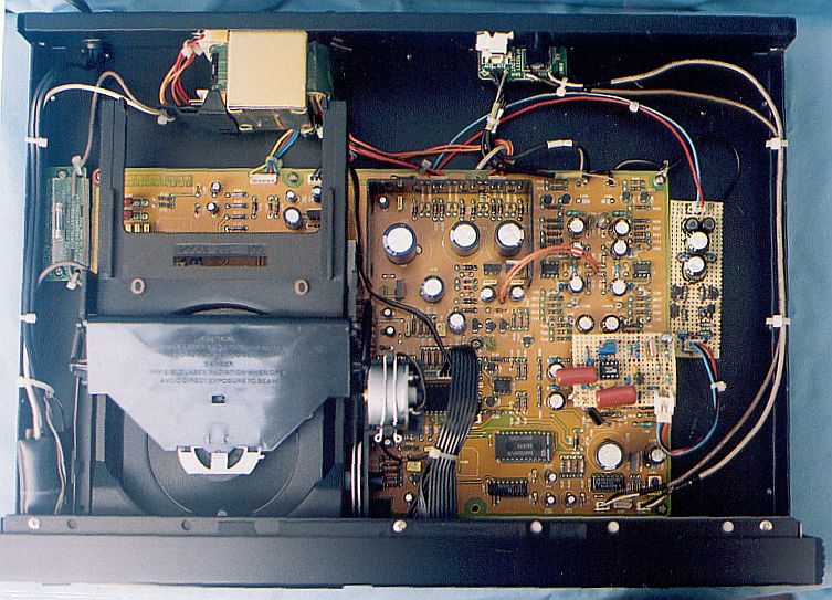
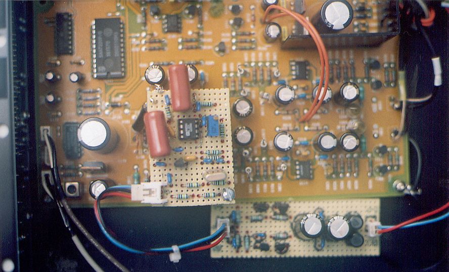
The small, square piece of perf-board you can see in the above photo that is mounted over the main CD board is the clock board. The crystal was removed from the CD player's circuit board and mounted on the clock board (the small, silver can-like object in the lower right part of the clock board), and the output from the clock board is routed to the CD player circuit board with a short piece of black, 75 Ohm digital coaxial cable that goes straight down. The long, thin piece of perf-board mounted along side of, and below, the CD board is the power supply to run the clock. The power supply is fed with +/-10 VDC from the CD player's digital power supply. |
|
| | | |
| |
The clock was designed and published by Elso Kwak, and is known as the "Kwak Clock". You can find the plans and specs for version 7 of the Kwak Clock in a zip file attachment to one of Elso's posts on the DIYAudio site (search for Kwak Clock). |
|
| | | |
| |
AC Mains Filter |
|
| | | |
| |
 |
| | | |
| |
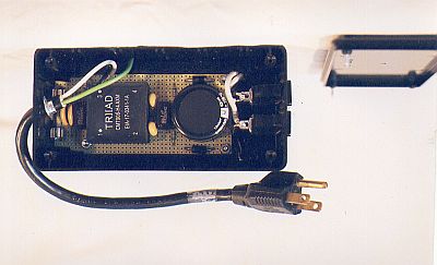
I also built a low-power mains filter on a piece of perf-board exactly like the one in the preamplifier and put it in a Radio Shack plastic project box along with two, two-pronged AC receptacles. I plug the three-pronged grounded filter cord into the wall, and then plug the CD player into one of the two-prong filtered receptacles. Filtered AC mains can't hurt the CD player's performance. |
|
| | | |
| |
Conclusion |
|
| | | |
| |
How does it sound? The addition of the clock definitely made the player sound a little smoother, and less harsh. When I first installed the new opamps, I'm not sure I could tell any difference, but I thought, what the heck; they were free. After I added the 22 uF and 100 nF capacitors and used the resistors to force the opamps into class A, I noticed a BIG difference. The music became more detailed; guitars sound more like real guitars, everything sounds more "live" and real. The highs became more pronounced, and I added another 2 ohms to the tweeters, so now it sounds excellent. |
|
| | | |
| |
Back |
|