| |
 |
| | | |
| |
Introduction |
|
| | | |
| |
I have always wanted a very high quality headphone amplifier. I did not include a headphone amplifier in either the preamplifier or the power amplifier because a quality headphone amplifier is too large and complex to be put in with either of those components. So, I built a separate unit that can be used with any of my sources by plugging it into the preamplifier's Tape Out jacks, and using the preamplifier's selector switch. The preamplifier and power amplifier do not need to be on when using the headphones (unless I'm listening to a phonograph album). To pull this off, I had to make some minor modifications to how the Tape Out jacks are wired. See the preamplifier page for details. |
|
| | | |
| |
I originally built this headphone amplifier using an IC-based OPA-2134 and BUF634 design as described here. However, after Santa brought me a new pair of excellent Sennheiser 580 headphones, I wanted to build a better amplifier using discrete parts instead of opamps. After much searching I settled on the so-called "Dynalo" Class-A discrete amplifier designed by Kevin Gilmore. The original Gilmore design was published on the old Headwize.com site (now gone) and it subsequently underwent numerous refinements, the results of which are discussed on several headphone DIY message boards, such as here. |
|
| | | |
| |
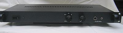
The headphone amplifier is a solid state device and is housed in a 1U rack case, the final resting place of the DAC/Active Crossover case. The front of the amplifier has an on/off switch, blue LED indicator light, crossfeed selector switch, volume control, and two headphone jacks (a 1/4" and a 1/8" jack wired in parallel). |
|
| | | |
| |
 |
| | | |
| |
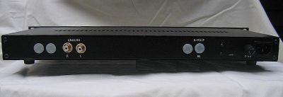
On the back are two gold-plated RCA input jacks on the left side, and a standard mains power connector and a 3/4 A fuse case on the right side. There are also several white hole plugs as a result of the case's previous service as a DAC and an Active Crossover unit. |
|
| | | |
| |
 |
| | | |
| |
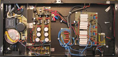
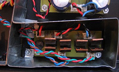
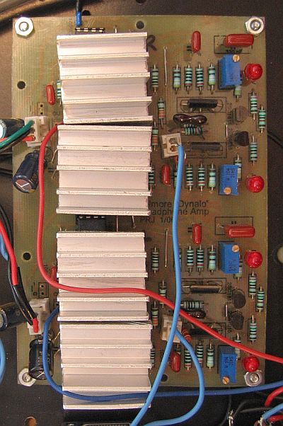
Inside the headphone amplifier case, the photo above shows the following, from right to left:
- AC mains input, fuse, filter, transformer, and power switch
- Shield plate
- Power supply and muting circuit board with adjacent floating star ground point, and the diode bridges at the bottom (front) behind a small piece of shielding
- Crossfeed circuit board with a selector switch on the front panel (removed 1/20/2013)
- Amplifier circuit board with the input RCA jacks on the back panel and the volume control on the front panel
- Muting relay board and headphone jacks on the front panel
|
|
| | | |
| |
AC Mains Circuits |
|
| | | |
| |
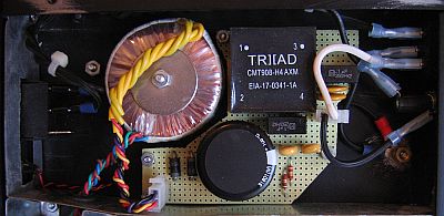
The hot AC mains lead is routed with 18 AWG stranded wire from the receptacle on the back panel (in the upper left corner of the above photo, right side of photo below), to the front panel rocker switch, back through the 1 A fuse case on the back panel, and into the mains filter board. The ground from the receptacle is attached to a chassis ground point immediately to the left of the mains filter board, with a brass bolt, washer, and nut assembly, attached directly to the case bottom panel. |
| | | |
| |
 |
| | | |
| |
The mains filter is built on a small piece of perf-board, and was designed to remove noise above about 27 KHz from the AC current. The filter uses two thin, yellow 130 VAC MOVs and two black, boxy, 100 nF X2/Y metallized film capacitors across the mains; two fat, yellow 2.2 nF Y2/X1 ceramic capacitors, one from hot to ground, and the other from neutral to ground; and two 470 KOhm resistors also across the mains. A 16 mH, 2.6 A, common-mode choke (the square, black box labeled TRIAD) is included in-line with both the hot and neutral lines to eliminate common-mode noise from the current. The large, low-voltage, high ripple-current, 12,000 uF electrolytic capacitor, protected by two opposite-oriented, high-current diodes, forms a "DC Trap" that eliminates an annoying 60 Hz buzz from the transformer that is caused by stray DC current in the AC mains. The ground wire from the filter is attached to the chassis ground bolt. |
| | | |
| |
The mains filter feeds a 15 VA toroidal transformer with two 15 VAC secondaries. The secondaries are not combined at this point to form the 0 V reference ground; the reference ground is created after the rectifying and smoothing circuits. The secondaries are routed separately to the dual rectifying circuits adjacent to the AC mains area. |
| | | |
| |
The secondaries are rectified individually, each with a separate diode bridge. Each bridge consists of four, OnSemi MSR860, 600 V, 8 A, soft-recovery diodes (the diode bridges were moved from the power supply board to an area adjacent to the AC mains area and put behind shielding to isolate them from the power supply and the amplifier circuit). |
| | | |
| |
 |
| | | |
| |
The AC mains filter, transformer, and diode bridges are isolated from the power supply board and the sensitive amplifier circuit by galvanized steel shields. The shields are electrically connected to the top, sides, and bottom of the case, thereby creating a "Faraday Cage" that shunts any noise emitted by the AC components and the diodes to the chassis ground so they do not effect the signal. |
| | | |
| |
Power Supply |
|
| | | |
| |
 |
| | | |
| |
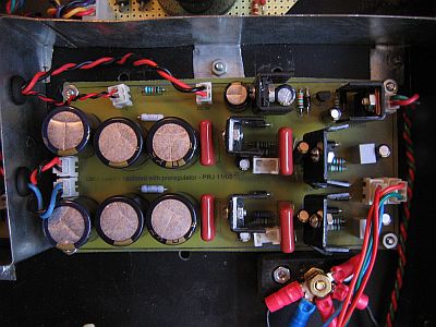
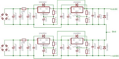
Each diode bridge feeds a separate smoothing circuit composed of three 2,200 uF Panasonic FC series electrolytic capacitors (7,200 uF total) separated by an in-line 10 ohm resistor, that is in turn followed by the two regulator circuits set up as a "tracking pre-regulator". |
| | | |
| |
The power supply is a standard, linear, regulated power supply that uses two sets of regulators. Each regulator circuit consists of a 100 nF polypropylene cap, an LT-1086 variable voltage regulator, and another 100 nF polypropylene cap. Each set of regulator circuits is followed with a 10 uF FC series electrolytic capacitor and a protection diode. Protection diodes are also included around the regulator ICs. |
| | | |
| |
The (+) output of one of the smoothing/regulator circuits is combined with the (-) output of the other to form a common 0 VDC reference that connects to the star ground point. The other outputs from the two circuits form the +16 VDC and -16 VDC rails. |
| | | |
| |
The first regulator in each smoothing/regulator circuit acts as a "tracking pre-regulator" that feeds the second regulator. The two regulators together produce the +/- 16 VDC. The "ground" segment from the first regulator circuit is connected to the output of the second regulator circuit. Both regulator circuits use the same set of resistor values that set the output voltage at 16 VDC. The "tracking pre-regulator" configuration is widely regarded to be superior to a single regulator (or two connected in series) because the first regulator (the pre-regulator) handles the current regulation, and the second regulator is then free to handle the voltage regulation. The result is a quieter, better regulated supply. The schematic is shown below. |
| | | |
| |
 |
| | | |
| |
The power supply gives a steady, very, very quiet supply, as shown here by my oscilloscope tests. |
| | | |
| |
The muting circuit is the same one used in the preamplifier, but here the components are included on the power supply board itself. The relay is mounted on a separate board immediately behind the headphone jacks on the front panel. |
|
| | | |
| |
Crossfeed Circuit |
|
| | | |
| |
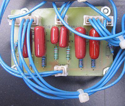 |
| | | |
| |
The signal from the RCA input jacks is routed directly to a 3-position, 3-deck rotary selector switch that controls the bass-enhanced natural crossfeed circuit. The crossfeed circuit that I used was developed by Jan Meier, and is described here. Basically, the circuit takes a small part of each channel, delays it 0.3 seconds, and merges it with the other channel. This simulates the way you hear stereo speakers where the two speakers are located on either side of your head. The crossfeed moves the stereo image out from the center of your head and eliminates the high-powered sound that is otherwise blasted directly into your eardrums. It sounds more natural, and it really cuts down on the fatigue you normally get from listening to headphones for long periods of time. |
|
| | | |
| |
Two of the three decks on the selector switch are used to control the crossfeed level for each channel, and the third deck is used to control the common bass-enhancement part of the circuit that connects the 30 nF or 47 nF capacitor to ground. The three switch positions control the degree of crossfeed: Low, High, or Off (bypass). |
|
| | | |
| |
The signal from the output of the crossfeed circuit is then routed through the 25 KOhm Noble volume potentiometer and into the amplifier circuit board. |
|
| | | |
| |
January 20, 2013: Ever since I completed this amplifier and began listening to it, I noticed that there was an intermittent hum in one of the channels, and that even when the crossfeed switch was on "Off" there was still some cross-feeding going on. The hum was not loud, and it came on only after running the amplifier for a while, until it was good and hot, and then it came and went with variable intensity. Sometimes I could make it go away by touching various things (input jacks, power fuse case, etc.). At first I thought it was DC on the line and I thought I could correlate it with the furnace fan coming on, but I have a DC blocker in the power supply, and why would it only be one channel? I figured it must be a weird grounding issue, but I couldn't track it down. Finally I was experimenting to see if disconnecting the input cables made a difference. When I pulled out one jack, with the crossfeed off, instead of just hearing music from one side of the headphones, I heard a mono version of the music in both sides of the headphones! It did this when either channel input jack was pulled out. So, I figure that the problem was in the crossfeed circuit, most likely the switch, or actually the way the switch is wired, because I have checked the circuit board a million times, and I know it is OK. I never liked the sound when the crossfeed was set to Low, and especially not High, so I disconnected the crossfeed circuit entirely, removed the circuit board, and re-routed the input cables directly to the volume control. Now it sounds better than ever, more clear, more dynamic, better rnage, and more separation between the two channels. Now I know that I had been listening to some level of crossfeed even when "turned off". I'll bet the hum is gone too, but only time will tell. |
|
| | | |
| |
Headphone Amplifier Circuit |
|
| | | |
| |
 |
| | | |
| |
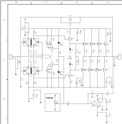
The amplifier circuit board is based on the PCB design provided by Gilmore in his original article, with a few modifications:
- Wire jumpers to avoid routing the (+) rail around the top of the board to the DC servo circuit
- Addition of film and electrolytic bypass caps according to the "Revision C" design
- Addition of 100 Kohm trimmer potentiometers around the input transistor bias resistors, also according to the "Revision C" design
- Addition of diodes for thermal stability, also according to the "Revision C" design, although I did not use them
- Addition of a 10 pF mica cap across the gain resistor to ward off oscillation, also according to the "Revision C" design
|
|
|
The schematic for one channel is shown below. |
|
| | | |
| |
 |
| | | |
| |
Each channel is completely independent with separate power supply connections, input and output connections, and DC servo circuits. |
|
| | | |
| |
I ordered 30 each of the 2SC1815 and 2SA1015 transistors so I could use the best matched sets of 12. I measured the Vbe and Hfe for each and chose the best matched pairs. I bought 15 LED's and used the four with the most similar values. I also matched the resistor values as best I could. |
|
| | | |
| |
After using the amplifier for about three years, I began to worry about the longevity of the output stage, because it runs in class A and the transistors get very hot (too hot to touch with your finger for more than about two seconds). Gilmore says that the transistors are supposed to get hot. My measurements with the scope (shown here) do not suggest that the amplifier is oscillating. I guess it is supposed to give off that much heat, but I know that if the transistors stay that hot for long, their lifespan will be drastically reduced. |
|
| | | |
| |
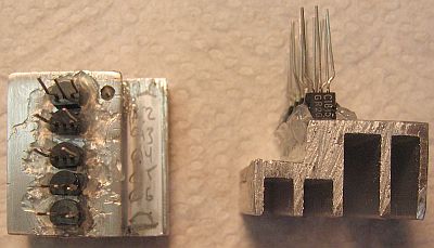
I decided to replace the VAS and output transistors, so I ordered 30 more each of the 2SC1815 and 2SA1015 transistors, and together with the leftovers from the first build, I was able to get better set of matched pairs than I did for the first build. In order to fight the heat, I decided to use heat sinks. I cut four small blocks from a piece of heat sink left over from trimming the heat sinks for the second power amplifier. I used heat sink grease to mount the tops of the transistors to the heat sinks, then glued the edges of the transistors to the heat sinks, as shown below: |
|
| | | |
| |
 |
| | | |
| |
I then inserted the whole row of transistors on each of the heat sinks into the PCB and soldered them all at once. |
|
| | | |
| |
For the DC servo opamps, I used TL081. I also tried TL071, but the TL081 provided better control. I was able to get the DC offset down to less than +/- 5 mVDC without the servo, and with the servos the DC offset is less than +/- 1 mVDC. It usually falls to just about 0 (+/- .1 mV) after 20 seconds or so. It can drift however; sometimes I've seen as much as 2 mV for a short time. |
|
| | | |
| |
Grounding |
|
| | | |
| |
A star-ground configuration is used. Signal grounds from the input jacks, the amplifier circuit board, the volume control, and the output jacks are run to the floating star point (located next to the power supply board near the rear panel), fed beneath the boards to keep the ground wires as close to the signal paths as possible. All power supply and ground wires are carefully bundled to prevent any open loops. Because the chassis is attached to the mains ground, the floating star point is not grounded to the chassis, and there is no perceptible hum in the output. |
|
| | | |
| |
Cables, Wires, and Connectors |
|
| | | |
| |
Internal wiring is 22 AWG hookup wire. Shielded cable between the input jacks and the crossfeed board, and between the amplifier output and the relay board, comes from decent-quality commercial interconnects. AC connections use Fast-On quick disconnects, or 9 A Molex Mini-Fit Junior plastic connectors with gold plated contacts. All DC power supply, signal, and ground connections use 3 A Molex-style plastic connectors with gold-plated contacts. |
|
| |
Cooling |
|
| | | |
| |
Because the amplifier runs in class-A, the output transistors and their heat sinks get quite hot. Heat is the enemy of electronic components, so to help with cooling, I drilled a bunch of ventilation holes in the case bottom, and in the case cover, directly over the row of output transistors. |
|
| | | |
| |
I also use a small Radio Shack 12 VDC fan. The fan is connected to the 12 VDC feed from the power supply to the output relay. A 220 Ohm resistor drops the fan voltage to about 9 VDC, the lowest voltage possible to keep the fan running, to minimize fan noise. You can clearly hear it when it is on, but you can't really hear it with headphones on, especially when music is playing. |
|
| | | |
| |
Over the years I have positioned the fan in different places to try to maximize cooling. I tried mounting the fan on the underside of the case cover, and I fashioned a small deflector that directed the air flow over the heat sinks, more or less. I tried mounting the fan inside the case, but it was too tall to stand vertically, so the air mostly went under the circuit board, and it just recirculated warm air within the case. |
|
| | | |
| |
I also tried drilling holes in the back of the case and mounting the fan on the back. The holes didn't let through enough air to matter, so I cut out a 1-inch-plus hole in the back and mounted the fan directly over it. The air flow can't be pointed straight at the heat sinks, but at least fresh, cooler air is going in to keep the temperature inside the case down. |
|
| | | |
| |
Conclusion |
|
| | | |
| |
How does it sound? Excellent. To my ears, the discrete amplifier sounds a bit nicer than the opamp-based one, but the difference is very subtle. I think that the opamp design is a little sharper and the discrete is a little warmer and easier to listen to. Which is better? I don't know, but I am very happy with the Gilmore amp, and I am glad to be able to use the OPA2134/BUF circuit to make a better portable amp as described here. The Gilmore amplifier certainly measures incredibly well, as you can see here. |
|
| | | |
| |
Notes: Over the years, I have removed the cross-feed board, and its front-panel switch, and I also removed four 100 uF bypass capacitors that I added to each rail. I had mounted them too close to the signal input, causing an anoying intermittent hum, described in more detail here. |
|
| | | |
| |
As of now (late 2016), it is impossible to get the input transistors used in this design. It is possible to use discrete 2SK170 replacements, if you can find them, with some modifications (see posts on the DIYaudio website. |
|
| | | |
| |
Back |
|


