| |
 |
| | | |
| |
Introduction |
|
| | | |
| |
The preamplifier is a solid state device built around the FirstWatt B1 Buffer preamplifier circuit. The B1 is a unity-gain, discrete buffer designed by the inimitable Nelson Pass at PassLabs, and discussed here on the DIYAudio forum. |
|
| | | |
| |
The case also contains Rod Elliot's high-quality Project 06 and Project 99 opamp-based phono preamplifier circuits, described below. |
|
| | | |
| |
This is the fourth preamplifier circuit that I have built, the third in this case. You can read about the third one here. This latest one is much improved over the others because it was designed by an audio Genius/Master/Guru, is discrete rather than opamp-based, and has a better power supply (isolated bridges and high-quality serial regulators). It sounds significantly better. |
|
| | | |
| |
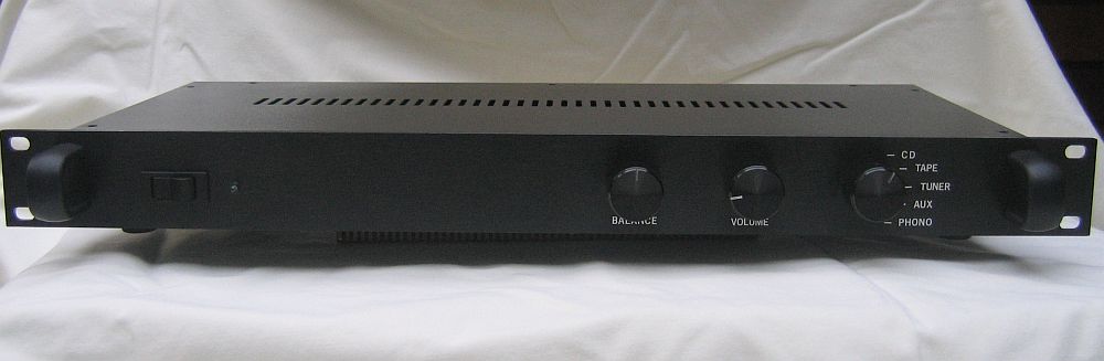
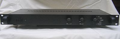
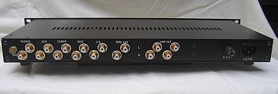
The preamplifier is housed in a 1U rack case. The front of the preamplifier has an on/off switch, a blue LED indicator light, a balance and volume control, and an input selector switch. |
|
| | | |
| |
 |
| | | |
| |
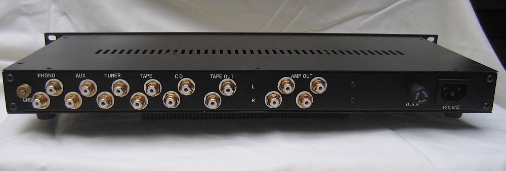
On the back, five sets of inputs are included, from left to right: Phono, Aux, Tuner, Tape Play, and CD. A set of Tape Out (record) jacks are included as well (see below). Two identical sets of output jacks (Amp Out) are also provided, one for the power amplifier, and the other for the subwoofer amplifier. All of the inputs and outputs are gold-plated RCA jacks. |
|
| | | |
| |
I no longer use my cassette tape deck, so I converted the Tape Out jacks to directly feed the signal from the selector switch to the Gilmore headphone amplifier (by removing the step-down resistors). Because the Tape Out jacks take their feed directly from the selector switch, the preamplifier does not need to be turned on when the headphone amplifier is used, except when using with the turntable, because the phono preamplifier requires power from the preamplifier power supply. |
|
| |
| |
Also on the back are a standard mains power connector and a 1 A fuse case on the right side, and a ground connector for the turntable next to the Phono input jacks. |
|
| | | |
| |
 |
| | | |
| |
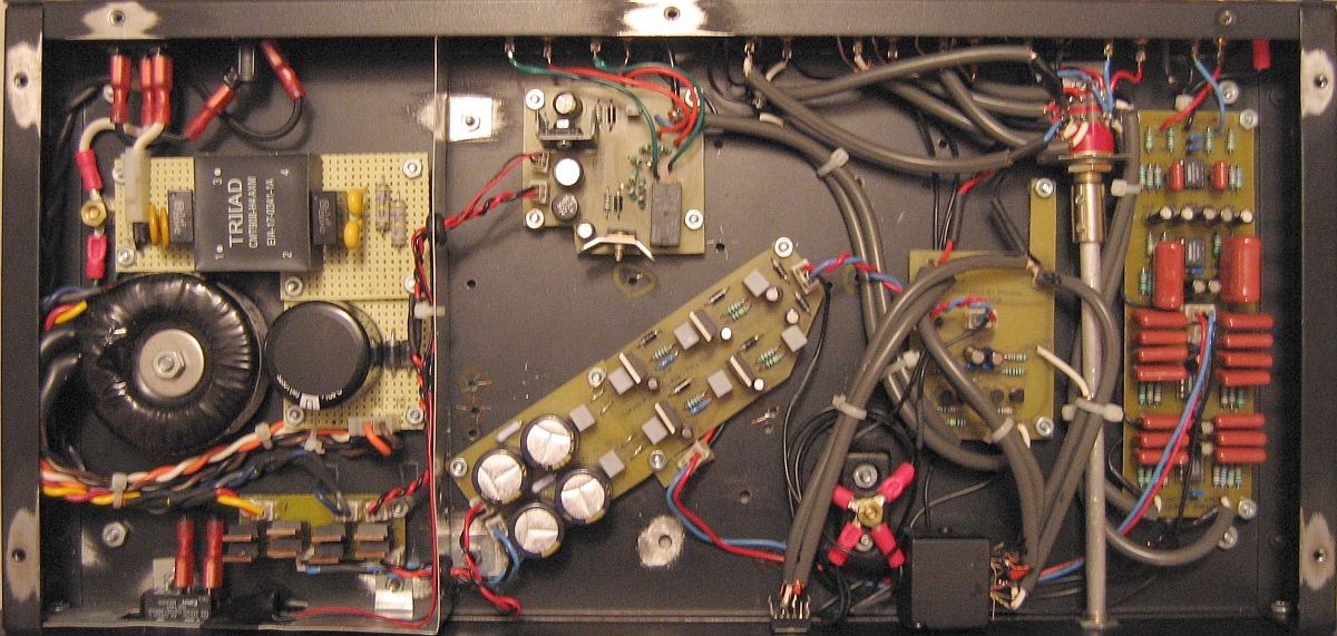
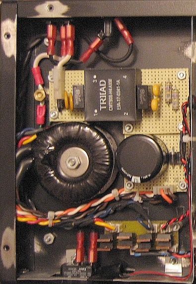
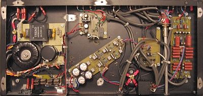
Inside the preamplifier case, the photo above shows the following, from left to right:- AC mains input, fuse, filter, and transformer, as well as the diode bridges at the bottom (front) of the case
- Shield plate
- Output muting circuit board (top), power supply circuit board (middle, slanted at an angle), and floating star ground point (bottom)
- B1 buffer circuit board
- Input selector switch and aluminum shaft
- Phono circuit board
- Input and output RCA jacks on the back panel
- Power switch, balance control, volume control, and input selector switch on the front panel.
|
|
| | | |
| |
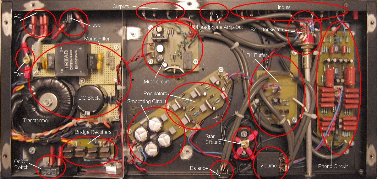
The picture below labels the various components (click to enlarge): |
|
| | | |
| |
 |
| | | |
| |
A Grayhill 6-position/2-pole rotary selector switch is used to control the inputs, and it is connected to the front-panel knob with an aluminum shaft. A high-quality 25 KOhm Noble potentiometer is used for the volume control, and the balance control is a high-quality conductive-plastic pot. Both the volume and balance controls use a simple divider /shunt design and are not in the signal path. |
|
| | | |
| |
AC Mains Circuits |
|
| | | |
| |
The hot AC mains lead is routed with 18 AWG stranded wire from the receptacle on the back panel (in the upper left corner of the above photo), to the front panel rocker switch, back through the 1 A fuse case on the back panel, and into the mains filter board. The ground from the receptacle is attached to a chassis ground point immediately to the left of the mains filter board, with a brass bolt, washer, and nut assembly, attached directly to the case bottom panel. |
|
| | | |
| |
 |
| | | |
| |
The mains filter is built on a small, L-shaped piece of perf-board, and was designed to remove noise above about 27 KHz from the AC current. The filter uses two thin, yellow 130 VAC MOVs and two black, boxy, 100 nF X2/Y metallized film capacitors across the mains; two fat, yellow 2.2 nF Y2/X1 ceramic capacitors, one from hot to ground, and the other from neutral to ground; and two 470 KOhm resistors also across the mains. A 16 mH, 2.6 A, common-mode choke (the square, black box labeled TRIAD) is included in-line with both the hot and neutral lines to eliminate common-mode noise from the current. The large, low-voltage, high ripple-current, 12,000 uF electrolytic capacitor, protected by two opposite-oriented, high-current diodes, forms a "DC Trap" that eliminates an annoying 60 Hz buzz from the transformer that is caused by stray DC current in the AC mains. The ground wire from the filter is attached to the chassis ground bolt. |
|
| | | |
| |
The mains filter feeds a Plitron 15 VA toroidal transformer with two 15 VAC secondaries. The secondaries are not combined at this point to form the 0 V reference ground; the reference ground is created after the rectifying and smoothing circuits. The secondaries are routed separately to the adjacent dual rectifying circuits. | |
| | | |
| |
The secondaries are rectified individually, each with a separate diode bridge. Each bridge consists of four, OnSemi MSR860, 600 V, 8 A, soft-recovery diodes. The diode bridges are behind the shielding for the AC mains area in order to isolate them from the power supply and B1 buffer circuit boards, as described below. |
|
| | | |
| |
The AC mains filter, transformer, and diode bridges are isolated from the power supply board and the sensitive preamplifier and phono circuits by a galvanized steel shield. The shield is electrically connected to the top, sides, and bottom of the case, thereby creating a "Faraday Cage" that shunts any noise emitted by the AC components and the diodes to the chassis ground so they do not effect the signal. |
|
| | | |
| |
Power Supply |
|
| | | |
| |
 |
| | | |
| |
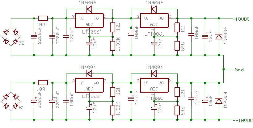
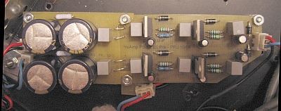
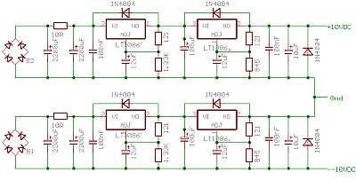
The power supply board, shown in the above photo, is a linear regulated power supply that uses two sets of regulators in series to drop the voltage to +/- 10 VDC. The schematic is shown below. Each diode bridge feeds a separate smoothing circuit composed of two 2,200 uF Panasonic FC series electrolytic caps separated by an in-line 10 ohm resistor, followed by a 100 nF polypropylene capacitor. The smoothing circuit is in turn followed by two regulator circuits in series. The first regulator circuit consists an LT-1086 variable voltage regulator, and a 100 uF FC series electrolytic capacitor, and it drops the voltage from about 24 VDC to about 16 VDC. The second circuit consists an LT-1086 variable voltage regulator, and a 100 nF polypropylene capacitor, and it drops the voltage from 16 VDC to 10 VDC (9.978 VDC, to be exact). The second regulator circuit is followed with a 10 uF FC series electrolytic cap and a protection diode. Protection diodes are also included around the regulators. The 100 uF electrolytic capacitor between the two regulator circuits keeps the power supply from oscillating, as I found out the hard way. |
|
| | | |
| |
The (+) output of one of the smoothing/regulator circuits is combined with the (-) output of the other to form a common 0 VDC reference that connects to the star ground point. The other outputs from the two circuits form the +10 VDC and -10 VDC rails. The power supply gives a steady, very quiet supply, as shown here by my oscilloscope tests. |
|
| | | |
| |
 |
| | | |
| |
Preamplifier Circuits |
|
| | | |
| |
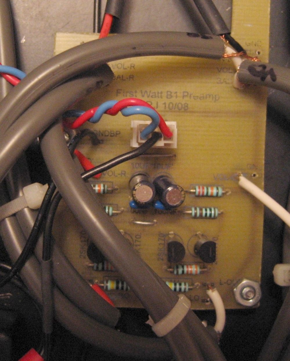
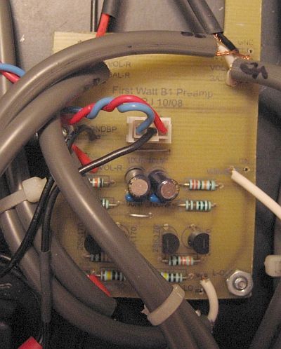
The preamplifier circuit board is shown in the picture below. The preamplifier receives the signal from the rotary switch and handles the volume and balance controls. |
|
| | | |
| |
 |
| | | |
| |
The preamplifier board is based on the FirstWatt B1 Buffer schematic found here. The B1 is a discrete design that uses 2SK170 transistors. I used the dual-supply, "capacitor-less" version developed by one of the posters in the B1 thread on the DIYAudio PassLabs forum. I used a +/- 10 VDC power supply because this was rumored to provide the best sound. The 2SK170 transistors were carefully matched for identical Idss (7.8). |
|
| | | |
| |
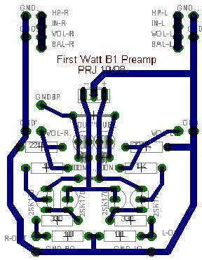
I designed the PCB layout myself (shown below) in the old Eagle freeware program, and I tried to keep the transistors as close to each other and thier related resistors as possible, and to keep the power leads separate and isolated, and to generally keep the signal path as short as possible. I also added 10 uF electrolytic and 100 nF ceramic bypass capacitors on the supply rails as close to the preamplifier circuit as was feasible. The ground connctions for the bypass cpacitors are independant of the main circuit ground, and are run separately to the star ground point. I didn't use a ground plane. |
|
| | | |
| |
 |
| | | |
| |
The design uses no capacitors (or servo) to control DC offset, and the two channels measure variably between 0 and 0.4 mA DC at the output. This poses no problem, because the amplifier has an imput capacitor to filter this out. The B1 has unity-gain, which means that I must turn up the volume a little bit more for the same sound level that I got with the OPA627-based preamplifier circuit (10 o'clock with the old cicuit is the same as about 11:30 with the B1) But I still have plenty of room to spare. |
|
| | | |
| |
 |
| | | |
| |
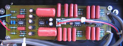
The combined RIAA phono circuit (ESP Project 06) and subsonic filter (Project 99) circuit board lies along the left side of the case as shown in the picture higher in the page, and as shown in the above picture. The phono preamplifier (left half) uses LM4562 opamps, and it makes my old records sound as good as, and in many cases much better than, the CDs. The subsonic filter (right half) uses a bank of 150 nF polypropylene capacitors and OPA2134 opamps to eliminate frequencies below 17 Hz. |
|
| | | |
| |
The phono preamplifier is designed to use +/- 15 VDC rails, however, because the B1 Buffer circuit is using +/- 10 VDC rails, the phono circuits were forced to use the same rails. Fortunately, the opamps are fine with operating at low voltages (such as +/- 4.5 VDC in portable headphone amplifiers), and I don't notice any decrease in quality from the +/- 10 VDC rails. |
|
| | | |
| |
Grounding |
|
| | | |
| |
A star-ground configuration is used. Signal grounds from the input jacks are collected for each channel at the rotary switch and run to the floating star point (located between the power supply board and the front panel), fed beneath the boards to keep the ground wires as close to the signal paths as possible. All power supply and ground wires are carefully bundled to prevent any open loops. Because the chassis is attached to the mains ground, the floating star point is not grounded to the chassis, and there is no perceptible hum in the output. |
|
| | | |
| |
The phono board and the preamplifier board each have two independent circuit grounds. The regular circuit grounds go from the boards to the star point, and the grounds from all rail bypass caps on the boards are kept separate from the circuit grounds, and are routed separately to the star point. The signal grounds are not connected to either board, but are routed directly beneath each board to the star ground point. All ground wires are tightly bundled with the power supply wires when possible to eliminate ground loops. |
|
| | | |
| |
Muting Circuit |
|
| | | |
| |
The output from the preamplifier board goes to a mute circuit near the output jacks, shown in both above photos. The mute circuit uses a direct AC feed from one of the transformer secondaries, and rectifies it to 12 VDC on the mute board. The DC is used to power the mute circuit, and to power the blue indicator light on the front panel, thereby keeping these circuits separate from the signal circuits. The mute circuit is an adaptation of the soft-start circuit originally published as ESP Project 39, before the circuit was modified for the pre-made PCBs. The circuit provides a half-second delay before energizing a small relay that disconnects the preamplifier output from ground. |
|
| | | |
| |
After the signal leaves the relay, it is split into two, and each split passes through a 100 ohm resistor before connecting to the RCA jacks. The 100 ohm resistors isolate the two outputs from the preamplifier circuit, and from each other, so the two amplifiers that are connected to the preamplifier can't "see" each other, and don't interfere with each other. Without the resistors, the two amplifier inputs would be connected directly together. |
|
| | | |
| |
Cables, Wires, and Connectors |
|
| | | |
| |
Internal wiring is 22 AWG hookup wire. Shielded cable between the input jacks and the selector switch, between the preamplifier and the volume and balance pots, and from the preamplifier to the mute circuit comes from decent-quality commercial interconnects. AC connections use Fast-On quick disconnects, or 9 A Molex Mini-Fit Junior plastic connectors with gold plated contacts. All DC power supply and ground connections use 3 A Molex-style plastic connectors with gold-plated contacts. All signal lead connections are soldered. |
|
| | | |
| |
Conclusion |
|
| | | |
| |
How does it sound? Extremely quiet and absolutely transparent. The highs and mids are noticeably clearer and cleaner than any of the previous opamp-based preamplifiers. This circuit made a very noticable imporvement in the sound of my system. The unit measures incredibly well, as you can see here. |
|
| | | |
| | | |
| |
Back |
|