 |
||
| Introduction | ||
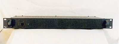
| The DAC (Digital-to-Analog Converter) is a solid-state device built from Randy McAlleny's design (as contributed to the ESP web site and published as Project 85). The DAC is housed in a 1U rack case identical to the preamplifier case. The front of the DAC has only an on/off switch and a green LED indicator light. | ||
| The circuit receives S/PDIF digital data from the digital-out jack of a CD player, via a 75 ohm coaxial cable, through a single RCA jack in the back. The analog output is run from the board to a pair of jacks on the back, that are then connected to the CD-in jacks on the preamplifier. The input and output use gold-plated RCA jacks. | ||
| The DAC contains two circuit boards, hand-wired on perf-board. A small board contains the power supply, and the other has the DAC circuitry and reset mechanism. | ||
| The power supply is fed from a 12 VDC, 1 A external transformer power-pack, and is protected with a 0.5 A fuse. It provides a steady +5 VDC from a low-noise LT1086 voltage regulator. The green LED indicator light comes off the 12 VDC input at the on/off switch. | ||
| DAC Circuits | ||
| The DAC circuit is built around two of Cirrus Logic's Crystal series IC's: the CS8414 digital receiver, and the CS4334 digital-analog converter chip. Both of these IC's are surface-mount-technology (SMT) SOIC devices, and they are TINY (the CS4334 measures only 2.5 mm by 5 mm and has 8 pins - the CS8414 has 28 pins). They are very hard to work with, especially to solder wires to. | ||
| The automated reset circuit uses a standard 555 timer chip to constantly reset the receiver chip whenever a digital signal is lacking. Without the automated circuit, the DAC would have to be manually reset each time it is turned on. | ||
| The input and output jacks are connected to the DAC board with the shielded Teflon cable described on the Cable and Wire Page. | ||
| Grounding | ||
| As in the other electronic components, a star-ground configuration is used. The digital-in and analog-out grounds are kept isolated from the chassis, and are connected to the DAC board. The digital and analog grounds are then returned separately to the power supply board. At the two power supply/DAC board ground connections, the two grounds are split off, and the digital and analog grounds are combined and connected to the chassis through a 100 ohm resister that is bypassed with a 100 pF ceramic capacitor. | ||
| Conclusion | ||
| How does it sound? The IC's used in this design are not state-of-the-art, nor are they the "best" available. However, they are still very high quality. I decided to rig up a test to compare the new DAC to my current cheap-o CD player. | ||
| I hooked up the DAC to the digital-out connection of my $65 DVD player, then connected the analog outputs to the AUX input on the preamplifier. I put identical copies of a CD in the CD player and the DVD player, played them both at the same time, and switched between them to compare. I was sure that the DAC would sound significantly better, since the components had to be far superior to those in the DAC portion of the POS mass-market Japanese CD player. But, as badly as I wanted for my new DAC to sound better, I have to honestly say that I could detect absolutely no difference what-so-ever between the two. Oh well, I learned something about digital circuitry, and it was fun to make. I have a digital-out jack on my computer's sound card, and I can use it for that. | ||
| DAC Specifications | |
|---|---|
| Digital Receiver | Cirrus Logic Crystal CS8414 |
| Receiver Specs | Decoding Rate - up to 96 kHz Clock Speed - up to 256xFs Sample Size - up to 24 bit Oversampling - 32x per channel |
| Digital/Analog Converter | Cirrus Logic Crystal CS4334 |
| Converter Specs | Conversion Size - 1 bit Clock Speed - up to 256xFs Sample Size - up to 24 bit Dynamic Range - 96 dB Distortion (THD+N) - -88 dB |
| NOTE: After completing this project and testing it with disappointing results, I added an output buffer circuit to try to improve the sound. I based the design on Pavel Macura's output buffer described here, and placed it between the CS4334's output and the output jacks. I built a small ESP Project 05 power supply to feed the circuit's OPA2134 opamp and BUF634 buffer (+/-15 VDC as opposed to the +5 VDC for the DAC itself). I replaced the 12 VDC power-pack with a 13 VAC one, and routed the transformer's secondary to the buffer power supply board, then took the feed to the DAC power supply board from the input pin of the positive voltage regulator (LM7815). The buffer greatly improved the sound - it now sounds significantly better than the "POS mass-market Japanese CD player" mentioned above, but it unfortunately does not sound better than the modified Rotel RCD965BX CD player that I now use. Oh well! | ||