| |
 |
| | | |
| |
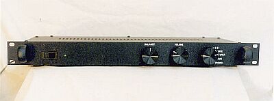
The preamplifier is a solid state device built around Rod Elliot's high-quality preamplifier circuits. The preamplifier is housed in a 1U rack case. The front of the preamplifier has an on/off switch, a green LED indicator light, a balance and volume control, and an input selector switch. |
|
| | | |
| |
 |
| | | |
| |
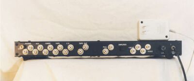
On the back, five sets of inputs are included: CD, Tape Play, Tuner, Aux and Phono. A set of Tape Out (record) jacks are included as well. A switch controls the preamplifier output, either the full signal to a single pair of jacks, or a split signal from an active crossover circuit that sends the > 60 Hz portion of the signal to the power amplifier, and the < 60 Hz signal to the subwoofer. All of the inputs and outputs are gold-plated RCA jacks. |
|
| | | |
| |
 |
| | | |
| |
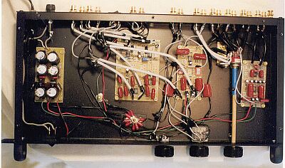
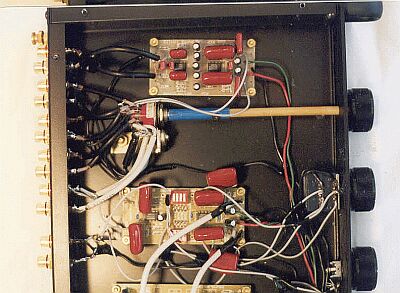
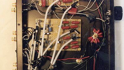
The preamplifier contains four printed circuit boards. From left to right these are: the power supply, the active crossover, the preamplifier itself, and the RIAA phono circuit. The power supply is fed from a 16 VAC, 1.5 A external transformer power-pack, and is protected with a 1 A fuse. |
|
| | | |
| |
A star-ground configuration is used. Signal grounds from the inputs are collected at the rotary switch and fed to the floating star point, as is the ground connection from each board. Output grounds are connected to the preamplifier, or the preamplifier and crossover. The star point is grounded to the chassis through a small resistor and capacitor. There is no perceptible hum in the output. |
|
| | | |
| |
A Grayhill 6-position/2-pole rotary selector switch is used to control the inputs, and it is connected to the front-panel switch with a wooden dowel. An Alps Blue potentiometer is used for the volume control, and the balance control is a high-quality conductive-plastic pot. Both the volume and balance controls use a simple divider design and are not in the signal path. The output switch is a high-quality, sealed, DPDT with silver contacts. |
|
| | | |
| |
The input jacks are connected to the selector switch with standard shielded cable. However, the CD input, the outputs from the preamplifier board to the output switch, from the output switch to the crossover board, and from the crossover to the output jacks, all use the shielded Teflon cable described on the Cable and Wire Page. |
|
| | | |
| |
 |
| | | |
| |
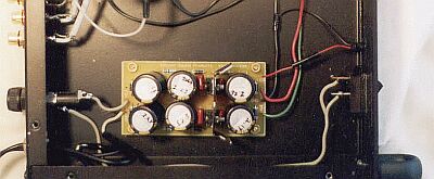
The power supply (ESP Project 05) provides a steady +/- 15 VDC that feeds the other three boards. Three 2,200 uF caps are used for each rail (13,200 uF total). A green LED comes off the power supply and is used as an indicator light on the front panel. |
|
| | | |
| |
 |
| | | |
| |
The RIAA phono board is shown at the top of the above picture. This board, ESP Project 06, is utterly superb. It makes my old records sound as good as, and in some cases much better than, the CDs. I almost didn't bother putting it in, but I am sure glad now that I did! I am currently in the process of digitally recording some of my favorite LPs and transferring them to CDR to replace the crappy 1980's CDs I have. |
|
| | | |
| |
Since the above photo was taken, I have added a subsonic filter (ESP Project 99) to remove effects caused by turntable rumble and warped records. The phono signal now goes from the phono board's output, through the subsonic filter, and into the selector switch. I hand-wired the circuit on a 2 inch square piece of perf board and installed it in the space between the phono board and the front panel. I used 220 nF capacitors, so the circuit removes all frequencies below about 12 Hz. |
|
| | | |
| |
The preamplifier board itself is below the phono board in the above picture. The preamplifier (ESP Project 88) receives the signal from the rotary switch, sends output to the Tape Out jacks and the output switch, and handles the volume and balance controls. The DIP switches on the board allow you to set the preamplifier gain. I currently have it set to a 5.2X gain. |
|
| | | |
| |
 |
| | | |
| |
The active crossover is a 12 dB/octave Linkwitz-Riley circuit (ESP Project 81). The crossover frequency is set at 60 Hz with 220 nF caps and 12.1k ohm resistors. I have the > 60 Hz channel set at minimum volume so the < 60 Hz signal will be strong enough to trip the auto-on feature of the subwoofer amplifier. |
|
| | | |
| |
As it turns out, I find that I don't like the sound from the crossover board. I am currently using a "Y" splitter on the full signal output jacks to route the signal to both the amplifier and the subwoofer. I am letting the crossover on the sub handle the 60 Hz cutoff duty. I find that this results in a fuller, richer, more even sound than that from the crossover board. |
|
| | | |
| |
How does it sound? Extremely quiet and crystal clear. There is no hum, no buzz, and no cross-talk between the inputs. As I stated above, the phono circuit is truly amazing. It is a fairly "minimalist" preamplifier with a minimum of circuitry (no loudness, tone controls, etc.) to degrade the signal. According to what I have read, the ESP Project 88 preamplifier is as good as any commercial offering on the market. I have not really evaluated commercial equipment of this kind, but my guess is that a store-bought unit with this sound quality would cost in the $600 to $1,000 range. |
|
| | | |
| | | |
| |  | |
| | | |
| |
NOTE: Since I completed the second preamplifier, I returned to this preamplifier and made the following modifications:
- Replaced the wooden dowel with an aluminum rod
- Added a muting board and relay for the output
- Removed the output switch
- Removed the crossover board
- Wired both sets of output jacks together
|
|
| | | |
| |
NOTE: In September of 2008, I used this preamplifier as a test bed for the new FirstWatt B1 buffer preamplifier circuit. The B1 is a unity-gain, discrete buffer designed by the inimitable Nelson Pass and discussed on the DIYAudio forum. I used a +/- 10 VDC power supply with 2SK170 transistors carefully matched, with no capacitors in the signal path. It sounded fantastic, so I built another one and installed it in the second preamplifier. |
|
| | | |
| |
Back |
|